Q2) Design a CT-FWR to supply a load of (502) with a waveform of the following specifications: - • Vdc = 12 V • Ripple factor = 0.1 % • the main power supply is (220 Vrms, 50 Hz). Determine the following values: - 1- The value of capacitor filter. 2- The maximum load voltage (VmR) 3- The transformer turns ratio (a). 4- The RMS value of the load voltage. 5- Draw the output waveform. (assume ideal diodes)
Q2) Design a CT-FWR to supply a load of (502) with a waveform of the following specifications: - • Vdc = 12 V • Ripple factor = 0.1 % • the main power supply is (220 Vrms, 50 Hz). Determine the following values: - 1- The value of capacitor filter. 2- The maximum load voltage (VmR) 3- The transformer turns ratio (a). 4- The RMS value of the load voltage. 5- Draw the output waveform. (assume ideal diodes)

Power System Analysis and Design (MindTap Course List)
6th Edition
ISBN:9781305632134
Author:J. Duncan Glover, Thomas Overbye, Mulukutla S. Sarma
Publisher:J. Duncan Glover, Thomas Overbye, Mulukutla S. Sarma
Chapter3: Power Transformers
Section: Chapter Questions
Problem 3.58P: A single-phase two-winding transformer rated 90MVA,80/120kV is to be connected as an autotransformer...

Related questions
Question
I need the answer as soon as possible
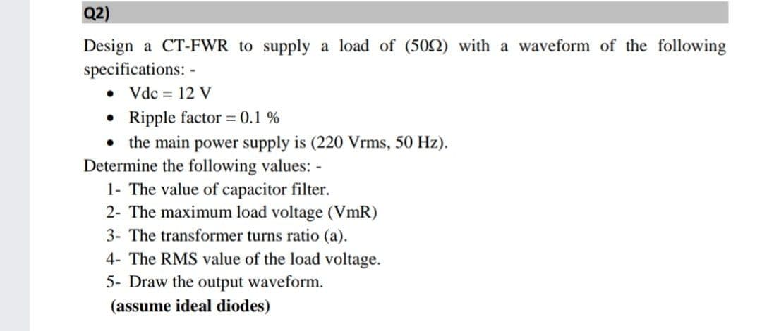
Transcribed Image Text:Q2)
Design a CT-FWR to supply a load of (502) with a waveform of the following
specifications: -
• Vdc = 12 V
• Ripple factor = 0.1 %
• the main power supply is (220 Vrms, 50 Hz).
Determine the following values: -
1- The value of capacitor filter.
2- The maximum load voltage (VmR)
3- The transformer turns ratio (a).
4- The RMS value of the load voltage.
5- Draw the output waveform.
(assume ideal diodes)
Expert Solution
This question has been solved!
Explore an expertly crafted, step-by-step solution for a thorough understanding of key concepts.

Step by step
Solved in 2 steps with 1 images

Recommended textbooks for you
Power System Analysis and Design (MindTap Course …
Electrical Engineering
ISBN:
9781305632134
Author:
J. Duncan Glover, Thomas Overbye, Mulukutla S. Sarma
Publisher:
Cengage Learning
Power System Analysis and Design (MindTap Course …
Electrical Engineering
ISBN:
9781305632134
Author:
J. Duncan Glover, Thomas Overbye, Mulukutla S. Sarma
Publisher:
Cengage Learning