the full-wave rectifier circuit of figure , the transformer has a turns ratio of 1:2. The transformer primary winding is connected across an AC source of 230V (rms), 50 Hz. The load resistor is 50ohms. For this circuit, determine the peak-to-peak ripple in the output voltage
the full-wave rectifier circuit of figure , the transformer has a turns ratio of 1:2. The transformer primary winding is connected across an AC source of 230V (rms), 50 Hz. The load resistor is 50ohms. For this circuit, determine the peak-to-peak ripple in the output voltage

Electricity for Refrigeration, Heating, and Air Conditioning (MindTap Course List)
10th Edition
ISBN:9781337399128
Author:Russell E. Smith
Publisher:Russell E. Smith
Chapter17: Commercial And Industrial Air-conditioning Control Systems
Section: Chapter Questions
Problem 22RQ

Related questions
Question
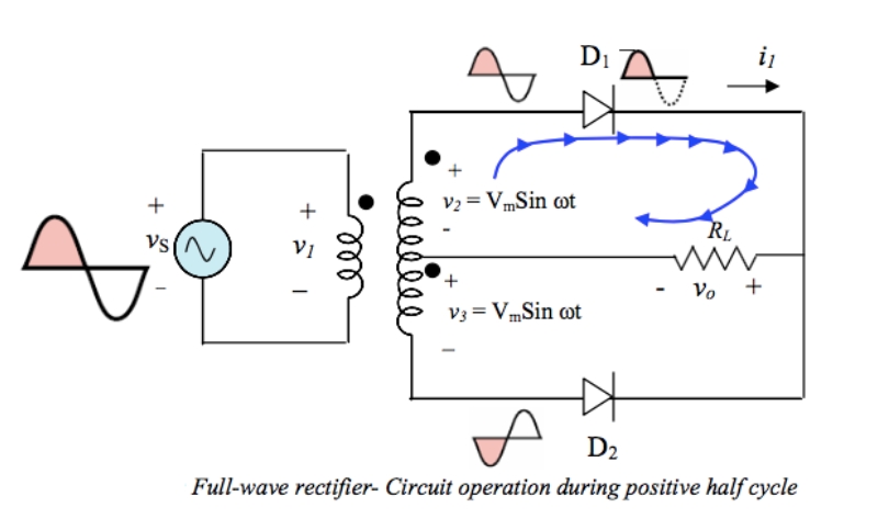
In the full-wave rectifier circuit of figure , the transformer has a turns ratio of 1:2. The transformer primary winding is connected across an AC source of 230V (rms), 50 Hz. The load resistor is 50ohms. For this circuit, determine the peak-to-peak ripple in the output voltage
Transcribed Image Text:Di
i
V2 = VmSin ot
+
RL
Vs(^,
+,
Vo +
V3 = VmSin ot
D2
Full-wave rectifier- Circuit operation during positive half cycle
all
Expert Solution
This question has been solved!
Explore an expertly crafted, step-by-step solution for a thorough understanding of key concepts.

This is a popular solution!

Trending now
This is a popular solution!

Step by step
Solved in 2 steps with 2 images

Knowledge Booster


Learn more about
Need a deep-dive on the concept behind this application? Look no further. Learn more about this topic, electrical-engineering and related others by exploring similar questions and additional content below.Recommended textbooks for you
Electricity for Refrigeration, Heating, and Air C…
Mechanical Engineering
ISBN:
9781337399128
Author:
Russell E. Smith
Publisher:
Cengage Learning
Electricity for Refrigeration, Heating, and Air C…
Mechanical Engineering
ISBN:
9781337399128
Author:
Russell E. Smith
Publisher:
Cengage Learning