Q2: For the beam shown in Figure (2), determine transverse shear stresses at points E, F and G on the cross section. The load P-100 kN and INA = 470016 mm². 12 mm H D B 0.2 m 0.4 m- 0.2 m 6mm 4mm 96 mm 48 mm 12 mm
Q2: For the beam shown in Figure (2), determine transverse shear stresses at points E, F and G on the cross section. The load P-100 kN and INA = 470016 mm². 12 mm H D B 0.2 m 0.4 m- 0.2 m 6mm 4mm 96 mm 48 mm 12 mm

Principles of Foundation Engineering (MindTap Course List)
8th Edition
ISBN:9781305081550
Author:Braja M. Das
Publisher:Braja M. Das
Chapter6: Vertical Stress Increase In Soil
Section: Chapter Questions
Problem 6.4P: Refer to Figure P6.4. A strip load of q = 900 lb/ft2 is applied over a width B = 36 ft. Determine...

Related questions

Question
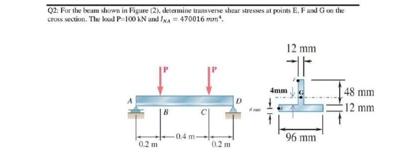
Transcribed Image Text:Q2: For the beam shown in Figure (2), determine transverse shear stresses at points E, F and G on the
cross section. The load P-100 KN and INA = 470016 mm².
12 mm
H
D
B
0.2 m
-0.4 m
0.2 m
6 m
4mm
96 mm
48 mm
12 mm
Expert Solution
This question has been solved!
Explore an expertly crafted, step-by-step solution for a thorough understanding of key concepts.

Step by step
Solved in 2 steps with 2 images

Knowledge Booster


Learn more about
Need a deep-dive on the concept behind this application? Look no further. Learn more about this topic, civil-engineering and related others by exploring similar questions and additional content below.Recommended textbooks for you
Principles of Foundation Engineering (MindTap Cou…
Civil Engineering
ISBN:
9781305081550
Author:
Braja M. Das
Publisher:
Cengage Learning
Principles of Foundation Engineering (MindTap Cou…
Civil Engineering
ISBN:
9781305081550
Author:
Braja M. Das
Publisher:
Cengage Learning