Q3 (A):- For the circuit shown in Figure (4), if B= 100, and r, = o, 1) Calculate the total voltage gain (Ays). 2) Determine the low cutoff frequency (F1). 20 R. 10 F 22k0 10 kn 20 F Figure (4)
Q3 (A):- For the circuit shown in Figure (4), if B= 100, and r, = o, 1) Calculate the total voltage gain (Ays). 2) Determine the low cutoff frequency (F1). 20 R. 10 F 22k0 10 kn 20 F Figure (4)

Electricity for Refrigeration, Heating, and Air Conditioning (MindTap Course List)
10th Edition
ISBN:9781337399128
Author:Russell E. Smith
Publisher:Russell E. Smith
Chapter11: Thermostats, Pressure Switches, And Other Electric Control Devices
Section: Chapter Questions
Problem 23RQ

Related questions

Question
I need the answer as soon as possible
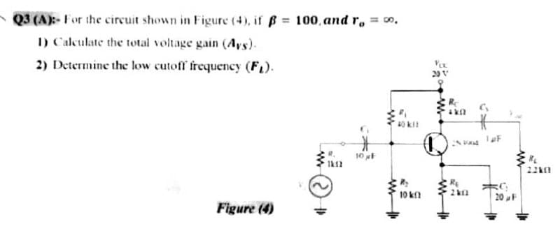
Transcribed Image Text:Q3 (A):- For the circuit shown in Figure (4), if B= 100, and r, o.
I) Calculate the total voltage gain (Ays).
2) Determine the low cutoff frequency (FL).
20 V
10 F
22k0
10 k
20 F
Figure (4)
Expert Solution
This question has been solved!
Explore an expertly crafted, step-by-step solution for a thorough understanding of key concepts.

This is a popular solution!

Trending now
This is a popular solution!

Step by step
Solved in 3 steps with 2 images

Knowledge Booster


Learn more about
Need a deep-dive on the concept behind this application? Look no further. Learn more about this topic, electrical-engineering and related others by exploring similar questions and additional content below.Recommended textbooks for you
Electricity for Refrigeration, Heating, and Air C…
Mechanical Engineering
ISBN:
9781337399128
Author:
Russell E. Smith
Publisher:
Cengage Learning
Electricity for Refrigeration, Heating, and Air C…
Mechanical Engineering
ISBN:
9781337399128
Author:
Russell E. Smith
Publisher:
Cengage Learning