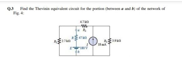
Q3 Find the Thevinin equivalent circuit for the portion (between a and b) of the network of Fig. 4: 4.7 kn R 47 kn R27kn 3.9k 18 mA E 180 V


Q: Applying 'Superposition Theorem', calculate I for the circuit shown in Fig.4 (b). 2KΩ 6KO 15 VA 30…
A: WE NEED TO DETERMINE THE DIRECTED CURRENT IN THE GIVEN CIRCUIT BY SUPERPOSITION THEOREM
Q: PRACTICE In the circuit of Fig. 4.4 and current division to find i, i2, and v3. use resistance…
A: Here basically we are interested to find first current i1 .
Q: Q2: For Fig. 4.37, calculate the voltage gain. Given that gm = 4 mA/V, rd = 45 kW, RD = 20 kW, and…
A:
Q: 4. Find the Thévenin equivalent circuit for the portion of the network in Fig. 4.7 kn Oa R2 RE 47 kn…
A:
Q: Q5/ Using a A-Y or Y-A conversion, find the current I in each of the networks in Fig. 5. w 4kfl www…
A:
Q: 4. For the network of Fig 4., Determine the range of R. and I that will result in VR being…
A: From the Zener Regulator Circuit
Q: 4.For the circuit shown in fig.4. Using superposition theorem, find the current through the resistor…
A: RESISTOR (R): A resistor is a passive electrical component with the primary function to limit the…
Q: Q4:- Find the Thévenin equivalent circuit for the network external to the resistor Rt for the…
A: Given data,
Q: 2Px 22 62 10 A b. Find the Norton equivalent circuit of the circuit in Fig. 4.45 at terminals a-b.
A: Given circuit,
Q: (a) For the circuit in fig 4, obtain the Thevenin equivalent at terminals a, b (b) Calculate the…
A: Note: "Since you have asked multiple question, we will solve first question for you. If you want any…
Q: Q5/ Using a 4-Y or Y-A conversion, find the current I in each of the networks in Fig. 5. www 4 kn…
A:
Q: Question(4): Forthe sirouit shown in Fig. 4, Find the value of V, using Theyenin Theorem.
A:
Q: 4. Write the mesh equations for the network in Fig 4 and solve for the loop currents by using…
A:
Q: Q6. Calculate the values of three currents in the circuit shown in Fig. 4. + Vcc = 10 V Re 2 k2 Ry=1…
A:
Q: Practice Problem 4.4 Use superposition to find v, in the circuit of Fig. 4.11. Answer: v, = 31.25 V.…
A: Given circuit,
Q: Q4 /( 25 Mark ) For the circuit shown in fig find the value of RL For maximum power , chen calculate…
A: In the diagram, we find the values of We know that to find the equivalent diagram we remove the…
Q: Q4:- Find the Thévenin equivalent circuit for the portions of the network in Fig. 5 external to the…
A: Solution: Thevenin voltage across ab: On applying KVL in the above loop:…
Q: Q4 Find Norton's equivalent circuit for the network of Fig. 5 external to resistor R 2.2 kn S mA 16…
A:
Q: In the circuit of Fig. 4.4 and current division to find i, i2, , use resistance combination methods…
A:
Q: Q4/ (6 Marks) In the circuit shown in Fig.4, apply mesh analysis to determine the current through 32…
A:
Q: Find i, in the circuit in Fig. 4.9 using superposition. www 4 A ww 20 V ww
A:
Q: 3.3 kl 120 mA 2.4 kN 1.2 kN Fig. P4.8 a.) Find the Norton equivalent circuit of Fig. 4.8 external to…
A: a) Find equivalent resistance across the load resistor R (Norton resistance) by open circuit the…
Q: Fi *4.68 Compute the value of R that results in maximum power transfer to the 10-N resistor in Fig.…
A: Disclaimer: Since you have asked multiple questions, we will solve the first question for you. If…
Q: Qi The sequences of voltage levels shown in Fig. 4.28 are applied to the summing amplifier.…
A: The op-amp is a device which ideally has very high input resistance. Hence, input current is zero.…
Q: 3. For the network in Fig. 4.21 Note: E is also equivalent to the designation Vs or Vr for voltage…
A:
Q: Q4: With reference to the circuit shown in Fig. 4, find the power absorbed by each of the seven…
A: We have given the following problem
Q: Question4i; For the circuit shown in fig(4), Determine the thevenin s equivelant circuit for the…
A:
Q: (2) „Ek In the circuit shown in Fig.4, the * current through 80 is 20 10 V 10 0 10 2
A: This circuit have one 10V battery source. Resistance are connected in series and parallel. Find…
Q: Q4. Given Vps=4 V for the network of the Figure 4, determine: a. Ip b. Vp and Vs c Vas 20 V 3 kn 1.2…
A: Fig: Given circuit (A) Apply KVL for loop 1 VDD-IDRD-VDS-IDRS=VSSplugging…
Q: Q4:- Find the Thévenin equivalent circuit for the network external to the resistor R. for the…
A: Given:
Q: a) Find the equivalent resistance and current (I) pass through the circuit shown in Fig. (4.a),…
A: Equivalent Resistance Req = 25 ohms. Current I = 1 Ampere. Explanation provided below. Please go…
Q: Find the resistance for the circuit shown in Fig. 4.42 ww
A: The solution can be achieved as follows.
Q: Example Use the superposition theorem to find v in the circuit of Fig. 4.6. 8Ω Solution: Since there…
A: Superposition theorem states that In a linear bilateral network containing more than one independent…
Q: I need the answer as soon as possible
A:
Q: Q2:- Find he therenin equivalent circuit For the network Shown in fig. 4u2 22 32 9.
A:
Q: Find the current 1,, V, and V for the network in Fig. 4 RI Хи X12 R1 I = 0.5 A 2 0º Xc, 20 %3D…
A: Clearly, from the given circuit the voltage across the inductor L1 is
Q: *33. Given Vg = 4 V for the network of Fig. 4.133, determine: a. VE. b. Ic c. Vc. d. VCE- e. Ig. г.…
A:
Q: Q.4: Using a A-Y or Y-A conversion, find the current I in the network of Fig. 4. 6 kN 4 ΚΩ 4 kN 400…
A: Given circuit,
Q: 9+16 V Emitter Bias Circuit 12 k2 For the network of Fig. 4.136, determine: a. Ip. b. Ic- c. VCE- d.…
A: In a BJT , we know that , Ic=βIbIe=βIb+IbVBE=0.7 Volt Now applying KVL from Base terminal to emitter…
Q: Question4): For the circuit shown in fig.(4), Calculate the current in the 62 resistor, using…
A: Need to find all.parts
Q: Practice Problem 4.4 Use superposition to find v, in the circuit of Fig. 4.11 20 2 Answer: v, = 25…
A:
Q: Q4- Find the Norton equivalent circuit for the network external to the elements between a and b for…
A:
Q: Use mesh analysis to find the current I in the circuit shown in Fig. 4. 16 N 6 0 j8 N 12 N 14 N…
A:
Q: Question4); For the circuit shown in fig(4), Determine the thevenin s equivelant circuit for the…
A:
Q: Q3/ For the circuits shown in Fig.4 and Fig.5, use Thevenin's theorem to calculate the current…
A: Thevenin's Theorem is a simple method to break down power circuits, which has a heap that changes an…
Q: 4 Determine the de level of In and Vc for the network of Fig. 4.42. 18 V 3.3 k2 10 μ 91 k2 110 k2 o…
A: In the question, Find the base current and collector voltage Vc? In DC analysis, capacitor act as…
Q: Q2:- Fined the therenin equivalent circuit For the network Shown in fig. 4u2 2 402 32 \2v
A: From the Thevenins equivalent Circuit
Q: 3. For the network in Fig. 4.21 Note: E is also equivalent to the designation Vs or Vr for voltage…
A: The required parameters can be calculated by using the basic laws of circuit analysis.
Q: Given the information appearing in Fig. 4.127, determine: a. Ic. b. VE- с. Vсс. d. VCE- e. VB- f.…
A: Collector current =beta×base current. Emitter current =base current +collector current. We will…
Q: Example 4.17 Calculate the value of the multiplier resistor for a 50 Vrms ac range on the voltmeter…
A:

Step by step
Solved in 4 steps with 3 images

- Write the KCL equations for the circuit shown Node b:Node c: Node g: Node f:A 620-V source connected to a resistor network described by RT = 50 + (R || 20) provides 120 V to the 20-ohm resistor. What is R?Using Kirchhoff's Rules, compute the current (mA) and voltage (V) values of the circuit if R1=2kΩ and R2=7kΩ.
- R1=560Ω, R2=1000Ω, R3=470Ω, R4=2200Ω, R5=1000Ω V1 =12V and V2 = 5V Calculate every current in the given circuit by using the superposition principle. ( IR1C=?, IR2C=?, IR3C=?, IR4C=?, and IR5C=?)For RL=180 ohms RL=470 ohms, find the VL, IL, IZ, IR voltages and currents and PZ power values separately. Briefly describe the operation of the circuit.In which one of Kirchhoff’s Laws does Mesh Analysis rely on? Give a detailed explanation for your answer
- QUESTION: Apply thevenin’s theorem for the network external to RL with all necessarysteps and formula. Draw the circuits required to find Eth and Rth. Finallydraw the thevenin equivalent circuit and find the current through RL if RL=10 kilo ohm.Thevenin's Theorem allows an electrical circuit to be represented by just a connected resistor in series to a voltage source. Consider for the circuit presented below: R1 = 5 kΩ ; R2 = 3 kΩ, R3 = 3 kΩ; R4 = 2 kΩ and VSource = 16 V. Determine, for this circuit, the values of VTh and RTh. answer: VTh = 8,0 V ; RTh = 5,5 kΩConsider the following circuit: If I1 = 13 A, I2 = 4 A, V1 = 12 V, R1 = 17 Ω, R2 = 16 Ω, RL = 4 Ω, what is the contribution of V1 to the voltage vx?
- In the circuit model shown, for R1=35, R2=76, R3=6, R4=14, R5=40, R6=2 & Vab = 20 v, find the following: Req at terminals a–b , i , vPerform the following steps for the given circuit in below.RD = RS = 1kΩ, R1 = 300kΩ, R2 = 100kΩ, VDD = +12V, IDSS = 12mA, VP = -4Va) Calculate the ID current, VDS and VGS voltage and determine the region of operationfor the JFET. (Hint: Use Thevenin’s Theorem)Which technique is most BW efficient? a. QPSK b. 32PSK c. 16QAM d. 8QAM