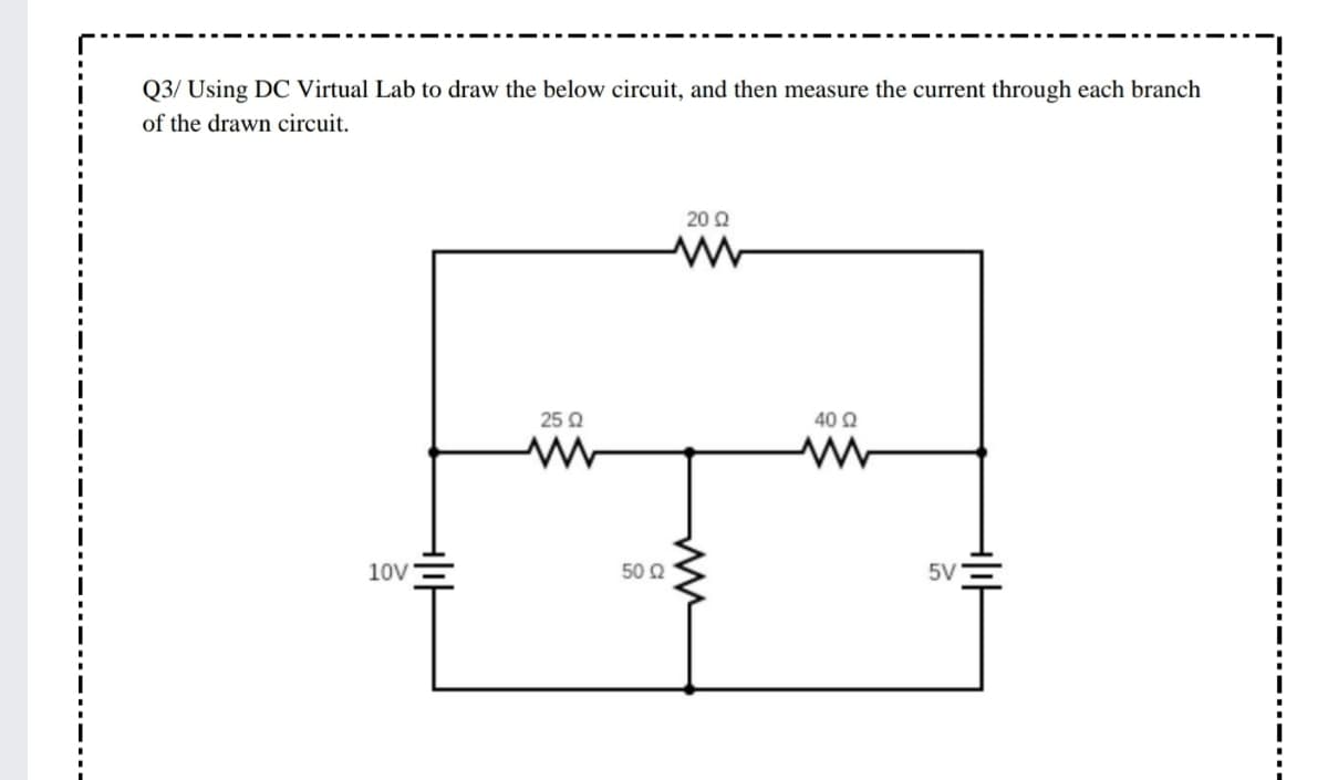
Q3/ Using DC Virtual Lab to draw the below circuit, and then measure the current through each branch of the drawn circuit. 20 Q 25 Q 40 2 10V 50 Q 5V


Q: 1. A solar cell has reverse saturation current is lo =4.3x 10 10 A and short- circuit current Isc =…
A: The open-circuit voltage of the solar cell is given by the expression as shown below:…
Q: 1-_ Find the margin of K to keep the system shown in figure N°1 stable R(s) E(S) K S s-1 s²+2s+1…
A: Given system,
Q: Write a state-space representation for the system in the following figure. Assume that the system's…
A:
Q: Consider the circuit shown in the figure below: 3i, WW OA 5 A 10 Ω The Thevenin's equivalent…
A: Given circuit is -
Q: input to the circuit shown below is the current…
A: In this question we will find voltage across 40 ohm...
Q: Consider the following circuit assume V = 1.2 V and k = 0.5 mA/V². th a. Determine I (in mA), VGs…
A: The solution is given below
Q: Q5. Find the initial value for the indicated current i,. 42 4 H 4ΩS 16TH 24 V (+ o 20 H
A: Given data,
Q: 7. For the circuit shown, the saturation current is a. 200 μΑ Re3.9 k2 b. 2.0 mA Rp Boc 200 Vcc 15 V…
A: Given,
Q: Derive the Thevenin equivalent circuit of the circuit shown in Figure below at the terminals a and…
A:
Q: 10 mH 5 k2 20 k2 12 µF 10 mA
A:
Q: Q3. For the circuit in the figure below, determine Vg and lĘ such that VB = Vc= BA/5, where BA is 52…
A:
Q: HELP I NEED THIS QUICKLY a:Write the equation Vo according to the block diagram given below. b:…
A: fig: Given block diagram Part (a )From above block…
Q: By assuming w = 1 rad/s, Calculation :Solve the circuit in Figure Q3 for V
A:
Q: In the circuit below, what is the value of the current 13? A 25 Ω F 0.52 A O 0.19 A O 0.71 A O 0.25…
A:
Q: For the circuit shown below, M1 and M2 are identical having Vtn = 0.5V and Kn'(W/L) =10 mA/V2. %3D
A:
Q: In the forllowing circuit, determine the value of the minimum base current required for saturation…
A: Given Betta = 50 Vcesat = 0.5 V ICsat = saturated collector current VLED = 1.5 V. IB…
Q: Report: 1. Refer to the experimental results compare the measured values with the calculated values.…
A: Resistance is the obstruction offered to the flow of current. The electrical element or the…
Q: A testing engineer while designing a HVDC source uses several modules of circuits having six stages…
A: Given: Input voltage V = 100kV = 105V Frequency f=100 Hz Load current I=1 mA=10-3A
Q: For this circuit, the values of 1, 12 and V are: 12 is 15 A R1 R3 R2 10 0 R4 10 Q Select one: O a.…
A: we need to find I1, I2 and V
Q: For the circuit shown, the value of RL so that İL = 5 mA is equal to. 1.5 k2 15 k2 20 mA( 15 kN RL…
A: we will use source transformation to reduce the circuit into single voltage source and we will find…
Q: Example: Derive the Thevenin equivalent circuit of the circuit shown in Figure below at the…
A: Thevenin theorem states that any linear network with multiple number of sources and multiple…
Q: نقطة واحدة the total resistance in the circuit shown in the figure is R 4 4Ω B C R4 0.5 2 E 10 V R4N…
A: the parallel combination of the resistances:-in case of the parallel combination of two resistances…
Q: Q2/ Using DC Virtual Lab to draw the below circuit and measure the total current and calculate RT…
A: In the circuit, In the DC current , total current in the circuit? Total resistance RT seen by?…
Q: 4. The NMOS in the circuit below has V10 = 0.6 V, y = 0.25 V/² and of = -0.30V. Find Vo. 2V o Vo CL…
A: Transistors : A semiconductor device that is used to boost electronic signals and electrical power.…
Q: Given the circuit below, determine the determine 13 R2 50 N 150 N R3 24 V 1000 R. 300 0 250 0 O…
A: According to the question we have to find the value of the current I3.
Q: For the circuit shown below, calculate the Notion's equivalent current IN external to the point's…
A:
Q: 2. By looking at the design and aspect of an Euler circuit, you can compare this type of circuit to…
A: Ans. Robotic circuit
Q: Find the total energy stored in the circuit of Figure below 602 L₁ = 2 mH 30 L₂=4mH C₁ = 20 µF C₂ =…
A:
Q: OSolve for Total voltage gain (Avı): +20V Ro 5 ks2 Ce 0.5F 20ka Ca 0.01uF los.-10mA V,=- 6V R. 3k2…
A: First we will find DC parameters then we will do ac analysis to calculate Gain .
Q: Determine the value of output voltage, Vo for the circuit in Figure Q3(a). Given the barrier…
A:
Q: "The initial energy stored in the circuit is zero. At t=0, a dc currentsource of 24 mA is applied…
A: The reactance offered by the inductor (XL) and capacitor (XC) and current supplied by the current…
Q: to Rc >1 k? R, 10 kΩ Vc VB 2N3904 ナ VE RE >1 k2 R2 4.7 kl
A:
Q: 5 R1 V2 What is V3 when Vbe = 0.7V, beta = 100, R2 = 1k, Vce(sat) = OV and R1 = 5k, what is the…
A: The solution is given below
Q: 3. Consider the time ot = 2r. a) What total energy, W, is stored in the circuit? b) Write the…
A: We need to calculate stored energy for given circuit . First we will find equivalent capacitor for…
Q: Consider the circuit shown in the figure below, R, = 20 and R, = 60 determine the value of the…
A: In the circuit Determine the current I in the circuit.
Q: For the circuit shown below, calculate the Notion's equivalent current IN external to the point's a-…
A: In this question we will find Norton current through ab...
Q: 1. For the system in figure below, N(s) G(s) Y(s). R(s) E(s) G2(s) G(s) H(s) Find R(sN=0 Y(s)…
A:
Q: 20µF R1 R2 Vc 0.5mH R3 12V 0.4mH 10μ 25V Assume the above circuit has been in this state for a very…
A:
Q: Q5. In a DC Bridge circuit shown in figure 1 is fed from a supply of 10V battery, if values of arm…
A:
Q: Q14. Obtain the equivalent resistance at the terminals a-b for the circuit in Figure Q14. ac 3100…
A: In this question we will find equivalent resistance across point ab...
Q: For the circuit shown below: B 100 and VBE = 0.7V, find: 7. IĘ 1. VE 2. Vc 3. VB 4. VBC 5. IB 8. Ic…
A: We have given the problem for the circuit shown find VE, VB, IB, IE, VC, VBC, IC
Q: نقطتان )2( For the circuit in figure below, the * :value of R1 is 2 A R1 R2 70 R3 17.50 140 V 15Ω Ο…
A: Given circuit,
Q: Problem 8.5-1 The circuit in the figure below contains a current-controlled voltage source. What…
A: The given circuit is, We need to calculate the thevenin equivalent resistance across the…
Q: Example: Derive the Thevenin equivalent circuit of the circuit shown in Figure below at the…
A: We know that current to voltage soruce transfrom By analysing the circuit From above…
Q: Kirchhoff's current law (KCL) is mostly to be applied to a circuit that are mostly closed to have…
A: Choose the correct options The given statment Kirchhoff current laws is mostly to be applied to a…
Q: Q3. For the circuit in the figure below, determine Va and le such that Va = Vc= BA/5, where BA is…
A: In the BJT circuit, Determine the value of VB and emitter current IE ? If VB = 19/5 Beta = 90…
Q: Q3. For the circuit in the figure below, determine VB and lĘ such that Vc= BA/5, where BA is 52…
A:
Q: %3D The circuit shown in the following figure is to be designed such that Ic= 2 mA and VCE= 2.0 V.…
A:
Q: a:Write the equation Vo according to the block diagram given below. b: Design the circuit that…
A: (a) Redraw the circuit diagram.
Q: U9 U92 A O US circuit shown below. Homework: Find the total resistance( Ry) and total…
A: We will reduce the given circuit into single voltage source in series with single resistor. This…

Step by step
Solved in 2 steps with 2 images


- Show complete and step by step solution. It is basic electrical engineering subj.In the circuit given in the figure VT = 25mV, | VBE | = 0.7V, R1 = 515.22Kohm, R2 = 10.89Kohm, R3 = 2.41Kohm, R4 = 1.03Kohm, VCC = 12.00V, VEE = 2.00V, VA = 12.51V, Beta Since = 107.00, Rs = 23.19ohm, Ry = 8.18Kohm, calculate the IC current, Ri, R0 and voltage gain according to the Source (V0 / V1) by making full analysis.In the circuit given in the figure VT = 25mV, | VBE | = 0.7V, R1 = 712.91Kohm, R2 = 43.27Kohm, R3 = 2.29Kohm, R4 = 0.98Kohm, VCC = 10.00V, VEE = -4.00V, VA = 10.06V, Beta = 137.00, Rs = 38.43ohm, Ry Calculate the IC current according to = 16.55Kohm, Ri, R0 and the voltage gain (V0 / V1) according to the Source by full analysis When making your transactions, 2 steps will be taken after the point. Select the closest option according to +/- 10% margin of error. There is only one correct answer to the question.
- A patient is coupled by 5pF stray capacitance to a 220V 50Hz ac power-line bus while his body is insulated from ground. The resistance experienced from the right side of the circuit, Za is measured to be 4MΩ.Find the voltage, Vo(t) and the voltage, Io(t) by usingphasor techniques.Q) Design a boost PWM converter to meet the following specifications: V;=30V, Vo=270V, R, =480 Q, f: =25 kHz, V,/Vo < 1%. Find L, C, minimum inductor current /y(min), maximum inductor current /y(max), and output power. Qa)Va = 27V, Vb = 45V, Ic = 4.0mA. The circuit is in dc steady state. Use superposition. Considering ONLY the contribution of the current source, Ic, Determine V1. Enter your answer in V rounded to one decimal place
- Q1) Conduct an evaluation on the practical applications of the concepts of electromagnetism and submit a written report which includes the following. a) Design a circuit which utilizes the concept of electromagnetism and submit a simulation circuit for the same (use simulation tool of your choice) b) Write down the selected values of the components used for example the values of resistors, transistor used, capacitors etc c) Obtain the output for the ciruit using any sinks like CRO, loud speakers etc. d) Discuss about the principles of electromagnetism used in the simulation I WANT QUESTION (D)The following are the readings taken while conducting an experiment on a wind turbine. what will be the value of open circuit voltage, if the short circuit current is 0.472 A, Maximum power point voltage is 5.32 V, Maximum power point current is 0.111 A and the fill factor is 0.599? Select one: a. 2080 mV b. 2.08 mV c. 8020 V d. 80.2 VIn the circuit given in the figure VT = 25mV, | VBE | = 0.7V, R1 = 950.31Kohm, R2 = 22.50Kohm, R3 = 2.51Kohm, R4 = 1.08Kohm, VCC = 13.00V, VEE = 3.00V, VA = 13.08V, Beta Since = 193.00, Rs = 22.94ohm, Ry = 14.49Kohm, calculate the IC current, Ri, R0 and the voltage gain according to the Source (V0 / V1) by making full analysis. When making your transactions, 2 steps will be taken after the point. Select the closest option according to +/- 10% margin of error. There is only one correct answer to the question.
- In the circuit model shown, for R1=35, R2=76, R3=6, R4=14, R5=40, R6=2 & Vab = 20 v, find the following: Req at terminals a–b , i , vIn the circuit given in the figure, Rk = 1.48Kohm, R1 = 7964.99Kohm, R2 = 7035.01Kohm, R3 = 2.46Kohm, R4 = 0.82Kohm, R5 = 24.08ohm, Ry = 98.63Kohm, VCC = 15.00V, VTN = 2.45V, Kn = Since 3.28(mA/V^2), C1= 6.30uF, C2=14.98uF, C3=10.96uF, calculate the lower cutoff frequency of the circuit in Hz.In the circuit given in the figure, Rk = 1.48Kohm, R1 = 7964.99Kohm, R2 = 7035.01Kohm, R3 = 2.46Kohm, R4 = 0.82Kohm, R5 = 24.08ohm, Ry = 98.63Kohm, VCC = 15.00V, VTN = 2.45V, Kn = Since 3.28(mA/V^2), C1= 6.30uF, C2=14.98uF, C3=10.96uF, calculate the lower cutoff frequency of the circuit in Hz. When making your transactions, 2 digits will be taken after the dot.