Q4/ For the figure below the spring is used to stop a 10 kg package. If the maximum deflection in the spring is 70 mm, (a) the total work of the system in the figure below is: (b): The total work when theta =0 equal to: * 8m/s Hk=0.25 K=400N/m 10kg 500m 0-30
Q4/ For the figure below the spring is used to stop a 10 kg package. If the maximum deflection in the spring is 70 mm, (a) the total work of the system in the figure below is: (b): The total work when theta =0 equal to: * 8m/s Hk=0.25 K=400N/m 10kg 500m 0-30

Mechanics of Materials (MindTap Course List)
9th Edition
ISBN:9781337093347
Author:Barry J. Goodno, James M. Gere
Publisher:Barry J. Goodno, James M. Gere
Chapter2: Axially Loaded Members
Section: Chapter Questions
Problem 2.8.4P: A block weighing W = 5.0 N drops inside a cylinder from a height h = 200 mm onto a spring having...

Related questions
Question
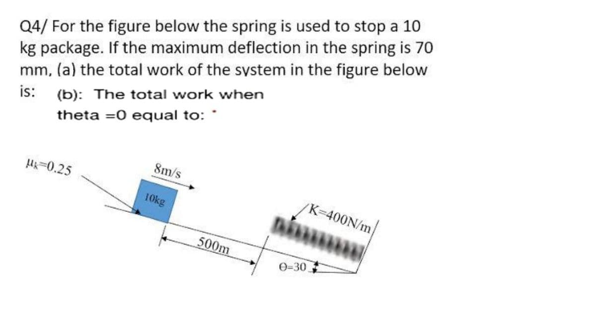
Transcribed Image Text:Q4/ For the figure below the spring is used to stop a 10
kg package. If the maximum deflection in the spring is 70
mm, (a) the total work of the system in the figure below
is:
(b): The total work when
theta =0 equal to: *
8m/s
H-0.25
K-400N/m
10kg
500m
0=30
Expert Solution
This question has been solved!
Explore an expertly crafted, step-by-step solution for a thorough understanding of key concepts.

Step by step
Solved in 2 steps

Knowledge Booster


Learn more about
Need a deep-dive on the concept behind this application? Look no further. Learn more about this topic, mechanical-engineering and related others by exploring similar questions and additional content below.Recommended textbooks for you
Mechanics of Materials (MindTap Course List)
Mechanical Engineering
ISBN:
9781337093347
Author:
Barry J. Goodno, James M. Gere
Publisher:
Cengage Learning
Mechanics of Materials (MindTap Course List)
Mechanical Engineering
ISBN:
9781337093347
Author:
Barry J. Goodno, James M. Gere
Publisher:
Cengage Learning