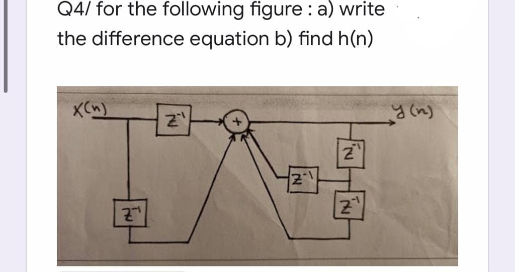
Q4/ for the following figure : a) write the difference equation b) find h(n) XCn)


Q: a) Sketch Vo versus time for the circuit shown with the input given. b) Determine DC output voltage…
A: The solution can be achieved as follows.
Q: 3. Consider a simple RC circuit with resistance R, capacitance C, and input voltage E(t). The…
A: The circuit this is excited the use of alternating supply is referred to as an AC Circuit. The…
Q: Q4) For the circuit shown, Find the output voltage and sketch it when the input voltage is 1v and…
A: The above circuit represents the op-amp Integrator. According to the given Input Waveform it…
Q: 4) Consider the following slew rate questions. Given a slew rate of I V/us, find the maximum…
A:
Q: Please write every step of your solution For the circuit given below find the operating point of the…
A: Given that V0=9 V, R1=3 ohm, e(t)=0.1sin(5t) VR=iR2-5iR-15 Now finding operating point (DC analysis)…
Q: Please write every step of your solution Find the SMALL SIGNAL COMPONENTS of the nonlinear 3-T…
A: In the question, the following circuit is given. Vs =V1 (because both are in parallel) so V1 = -6…
Q: x(t) A- T, Az- The given figure Iis a graph of one fundamental perlod of a perlodic function x(f). A…
A: Given: Brief description: In the given question they want to know the average value of the given…
Q: 13.13 An op amp with f, = 1 MHz has a phase margin of 80°. If the excess phase shift is due to a…
A:
Q: Find the energy stored in each capacitor andinductor, under steady-state conditions, in the…
A: It is known that the capacitor behaves as an open-circuit and the inductor behaves as a short…
Q: 300K 300K L=.3 dB 35K G = 25 dB 3dB G = 30 dB Find Cascade Gain in dB & real: 400k
A: As given in…
Q: - For the signal flow graph shown in figure X3/X1 0.5 10 X3 0.5 O 21 О 1 10.5 zero 10 11.5 no one of…
A: Signal flow graph X3/X1? We are solving this problem using masson gain formula
Q: Reduce the block diagram given in Figure 1 to a single block and obtain its transfer function or…
A:
Q: Q4: Design a buck-boost converter to provide an output voltage 12V from a source that varies…
A: Given V0 = 12 V Vs =10 V -16 V Load resistance, R=102 Ω (note: unit of resistance is not given. we…
Q: 5 k2 ww O mV ind the output of the op amp circuit sh Q+ 10
A: According to question:
Q: Consider the circuit shown below and answer all of the following questions. iR t = 0 10Ω V, = %3D 20…
A:
Q: Consider the circuit shown in Figure P4.64 in which the switch has been open for a long time prior…
A: Since we only answer up to 3 sub-parts,we will answer the first 3. Please resubmit the question and…
Q: Consider the circuit shown in Figure P4.64 in which the switch has been open for a long time prior…
A: Since we only answer up to 3 sub parts, we will answer the first 3.Please resubmit the question and…
Q: Design a switched capacitor circuit that could be used to synthesize a 100 k2 resistor where the…
A: A switched-capacitor (SC) is a filtering device in an electrical circuit. When switches are opened…
Q: Function signal generator has a wide range of applications in electronic measurement and teaching.…
A: The circuit diagram for getting square waveform is shown in the below figure:
Q: Find the output voltage V, of the Op-Amp circuit shown in the following Fig.P6 ww 6 kl V1 ww 2 kn m…
A: Image_1.jpg
Q: oneywell's Hall Effect Handbook (https://sensing.honeywell.com/hallbook.pdf) lists umerous…
A: Digital output hall effect sensor are primarily used in magnetic switch applications to provide a…
Q: 5.4 Figure P5.4 illustrates a parallel T null circuit. Find the frequency , at which the V.0. R R…
A: Given the circuit, as shown below: We need to find the frequency ω0 at which the Vo→0.
Q: R, ww R, ww out ROM For represented circuit sketch s-domain equivalent and compute the condition of…
A:
Q: - Determine the state equations ané alp equation far -The system below) - 2 4.
A:
Q: For the Op-Amp circuit shown below, v, (t) = 0.02 sin 200t V and vz(t) = 0.03 sin 200t V. Determine…
A: Given For Op-amp circuit V1(t) = 0.02sin(200t) v V2(t) = 0.03sin(200t) v Hence the output…
Q: Consider the circuit depicted in figure. If Vs(t) =-8+2u(t).determine: Vc(0+), iL(0+),…
A: Given Circuit
Q: Problem 3: 4 Design a buck-boost converter to meet the following specifications. Assume that the ESR…
A:
Q: A discrete-time system has an l/O description of y(n) = ny(n – 1) + x(n). Determine and sketch the…
A:
Q: R(s) + 100 (s + 5) s(s+ 3)(s² + 4) System 4 FIGURE P10.1 c-) Find the gain margin and phase margin…
A:
Q: 2. If Z,(s) is the impedance of 10 µF capacitor and Z2(s) is the impedance of 10ok2 resistor, find…
A:
Q: From the signal flow graph shown in the figure, the value of x, is x, a a d
A: Referring to the given figure:
Q: Consider the differential equation: y" What is the complementary function Ye = ce* + c2xe* Ye = c1…
A:
Q: For an input of V1 = 50 mV in the circuit below, determine the maximum frequency that may be used.…
A:
Q: (b) Derive the transfer function for the electric system shown. Draw a schematic diagram of an…
A: Write the expressions for KCL in the loop.
Q: H.W (13): For the circuit shown, determine: E R. ? E R. ? RE Rc If a = 0.99 Bo VCE = -7 V, VEEF4 V…
A: Givenα=0.99VCE=-7 vIE=1.1 mA
Q: 4 For the sequences x1(n) = cos -n. x2(n) = sin -п, 0<n<N-1 N N determine the N-point: (a) Circular…
A: According to our guidelines, we can answer only three subparts at a time. Kindly, repost the…
Q: G2 R H1
A: We need to find out transfer function for given system
Q: Consider the circuit shown in Figure P4.64 in which the switch has been open for a long time prior…
A: Hello. Since your question has multiple sub-parts, we will solve the first three sub-parts for you.…
Q: a) Sketch Vo versus time for the circuit shown with the input given. b) Determine DC output voltage…
A: We assume diodes are ideal. Given
Q: a) Referring to Figure Q2(a), perform the following. i) Determine the capacitance values required to…
A: (a) Given, Critical frequency =2.09 kHzResistance value=1.9 kΩNow, the critical frequency is given…
Q: Q6. For the circuit shown below, find the output d.c. voltage. F 10:1 Vpcin) D1 you D3, Vsec 115…
A:
Q: A power suppply having 220 V AC input and two fixed outputs as 10 V DC and 20 V DC is requested from…
A: A transformer is an electrical machine that is used in an AC circuit to either step up or step down…
Q: 4. First, obtain a mathematical model for the electric system shown below. Then, write the transfer…
A:
Q: Derive the differential equation that describes the output y() at capacitor C3 in (c) Figure 4.…
A:
Q: a) Sketch Vo versus time for the circuit shown with the input given. b) Determine DC output voltage…
A: The solution can be achieved as follows.
Q: Q4 Design a DC-DC converter which has an output of 10V from an input of 18V. The output power is…
A: Given that Vo=10V, Vin=18V, Po=10W∆Vp-p≤100mVα=2, F=2
Q: Q.1. A power suppply having 220 V AC input and two fixed outputs as 10 V DC and 20 V DC is requested…
A: Understand the problem statement by means of a block diagram, 15V AC is to be dropped to 10V DC and…
Q: For the following op-amp circuit, find the complex power and power factor angle associated with the…
A: As the given op-amp is ideal, it follows the virtual ground property. Write the value of the voltage…
Q: Can you give at least 2 similarities and differences of RC and RL Circuits which are not yet…
A: Difference in the RC and RL circuit:


Step by step
Solved in 2 steps with 2 images


- A. Give 3 possible problems rn that can relate on electrical engineering and give a solution that can aware public."determine Vo and Id" Please help me solve the following electronics exerciseDesign a combinational circuit with three inputs (E,L,Y) and three outputs (F,R,A). If the input is less than 5, then the output is 2 greater than the input. Otherwise, the output is 3 less than the input. if E=0 L=0 and Y=0, then if E=0 L=0 and Y=1, then if E=0 L=1 and Y=0, then if E=0 L=1 and Y=1, then…
- Explain the following systems (figure and transfer function): a) open loop systemsb) closed-loop systems1) Plot the root locus of the below system. 2) Give the value of the gain K where the response of the system will not have oscillations.Design an amplifier circuit using OPAMP with vo= (5*v1)+(v2)+(3*v3)-(2*v4). Draw vo knowing that v1 = 1 sin (1000*pi*t), v2 = 2 sin (2000*pi*t), v3 = 3sin (3000*pi*t), v4 = 4 sin (4000*pi*t)
- subject: Communication Fundamentals Modulation and Demodulation (give solve sub-parts iv and v)ELECTRONIC CIRCUIT ANALYSIS AND DESIGN Please give the step-by-step solution for this problem. Thank you! Note: Neglect VbeIs it possible to get a gain less than unity using a non-inverting amplifier configuration? If yes, sketch a circuit.''please solve it in computer font, not on paper''
- Draw the DC equivalent circuit and find re, VB, Vc, VE, VEc, VcB. Show all the necessary derivations and label all the parameters properly.Q.1. A power suppply having 220 V AC input and two fixed outputs as 10 V DC and 20 V DC is requested from you. For this purpose, a transformer with 220 V AC input / 15 V AC output, some capacitors, some silicon diodes, and zener diodes are presented.a) Design your power supply and point out DC voltage outputs b) Explain the operation of the network and all the components used in the design .c) Calculate and plot input and output signals of the network.Hint: For design, remember clipper, clamper, rectifier,voltage multiplier and zener circuitsThe voltage gain of an amplifier is described bythe transfer function has an inputvi = 0.002 sin ωt V. Write an expression for theamplifier’s output voltage at a frequency of (a) 5 Hz,(b) 500 Hz, (c) 50 kHz.