Q8. For the second order system shown below: 1. Range of gain (kl, k2) for which the closed-loop system in is stable should be obtained precisely. 2. Plot the range of the-k, on the real axis and k, on the imaginary axis. 3. Assume (k, = k, u-1),compute the ESS.
Q8. For the second order system shown below: 1. Range of gain (kl, k2) for which the closed-loop system in is stable should be obtained precisely. 2. Plot the range of the-k, on the real axis and k, on the imaginary axis. 3. Assume (k, = k, u-1),compute the ESS.

Power System Analysis and Design (MindTap Course List)
6th Edition
ISBN:9781305632134
Author:J. Duncan Glover, Thomas Overbye, Mulukutla S. Sarma
Publisher:J. Duncan Glover, Thomas Overbye, Mulukutla S. Sarma
Chapter12: Power System Controls
Section: Chapter Questions
Problem 12.3P

Related questions
Question
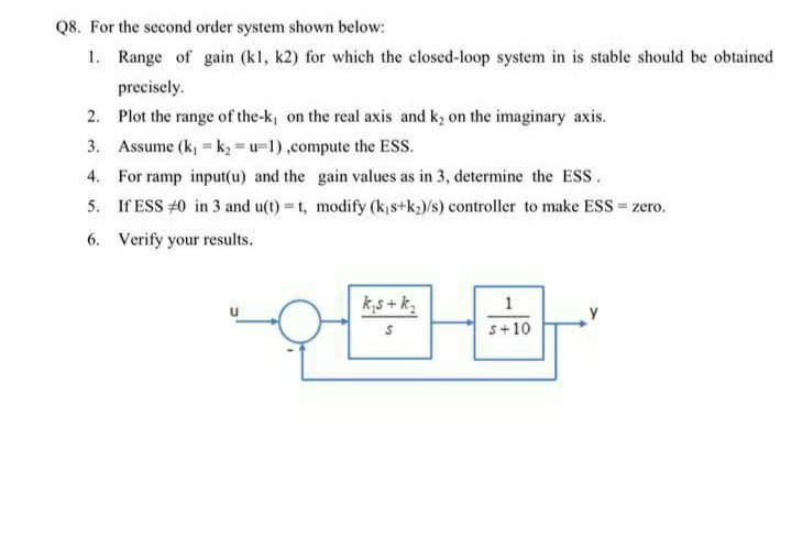
Transcribed Image Text:Q8. For the second order system shown below:
1. Range of gain (kl, k2) for which the closed-loop system in is stable should be obtained
precisely.
2. Plot the range of the-k, on the real axis and ky on the imaginary axis.
3. Assume (k, k = u-1),compute the ESS.
4. For ramp input(u) and the gain values as in 3, determine the ESS.
5. If ESS #0 in 3 and u(t) = t, modify (k,s+k)/s) controller to make ESS = zero.
6. Verify your results.
k,s + k;
1
s+10
Expert Solution
This question has been solved!
Explore an expertly crafted, step-by-step solution for a thorough understanding of key concepts.

Step by step
Solved in 2 steps with 2 images

Knowledge Booster


Learn more about
Need a deep-dive on the concept behind this application? Look no further. Learn more about this topic, electrical-engineering and related others by exploring similar questions and additional content below.Recommended textbooks for you
Power System Analysis and Design (MindTap Course …
Electrical Engineering
ISBN:
9781305632134
Author:
J. Duncan Glover, Thomas Overbye, Mulukutla S. Sarma
Publisher:
Cengage Learning
Power System Analysis and Design (MindTap Course …
Electrical Engineering
ISBN:
9781305632134
Author:
J. Duncan Glover, Thomas Overbye, Mulukutla S. Sarma
Publisher:
Cengage Learning