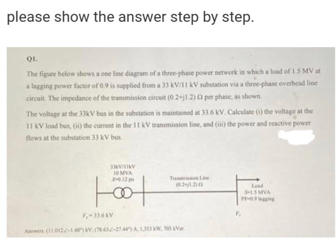
QI. The figure below shows a one line diagram of a three-phase power network in which a load of 1.5 MV at a lagging power factor of 0.9 is supplied from a 33 kV/11 kV substation via a three-phase overhead line circuit. The impedance of the transmission circuit (0.2+j1.2)Q per phase, as shown. The voltage at the 33kV bus in the substation is maintained at 33.6 kV. Calculate (1) the voltage at the 11 kV load bus, (i) the current in the 11 kV transmission line, and (iii) the power and reactive power flows at the substation 33 kV bus.


Short Transmission Line
A short transmission line is a transmission line that has a length less than 80 kilometers, an operating voltage level of less than 20 kV, and zero capacitance effect.
Power Flow Analysis
Power flow analysis is a topic in power engineering. It is the flow of electric power in a system. The power flow analysis is preliminary used for the various components of Alternating Current (AC) power, such as the voltage, current, real power, reactive power, and voltage angles under given load conditions and is often known as a load flow study or load flow analysis.
Complex Form
A power system is defined as the connection or network of the various components that convert the non-electrical energy into the electric form and supply the electric form of energy from the source to the load. The power system is an important parameter in power engineering and the electrical engineering profession. The powers in the power system are primarily categorized into two types- active power and reactive power.


Trending now
This is a popular solution!

Step by step
Solved in 3 steps


