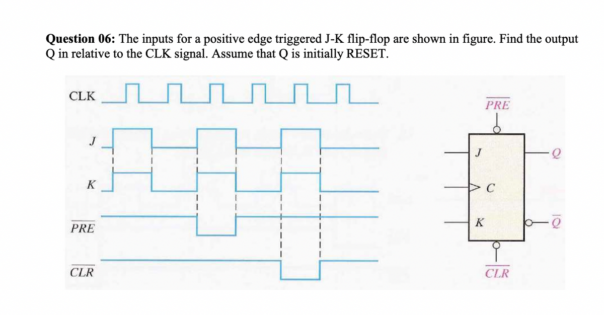
Question 06: The inputs for a positive edge triggered J-K flip-flop are shown in figure. Find the output Q in relative to the CLK signal. Assume that Q is initially RESET.


Q: Determine whether the following functions can be PSD of real-valued WSS random process. a. (1+10f)…
A: C)
Q: Explain each circuit on how it works and its output
A: We have to explain the given circuit. The given circuit is drawn in Proteus software.
Q: Drive efficency of spWM Converter.
A: Note: In the question, It is not mentioned efficiency means what exactly we have to determine.…
Q: The pylons of a high voltage line are 100 m apart and 16 m high. Line cables should not be less…
A: The pylons are 100 m apart. The height of the pylon is 16 m. The cable should be at least 6 m…
Q: Consider the AC circuit below. The o of the source is a rad/s and the system is in steady state. The…
A:
Q: (3) The system is in steady state. Find ia(t). (In your answer, combine cosines/sines with the same…
A:
Q: find the margin and phase margin for K = 10,000 from the Bode plot Please answer it only only…
A:
Q: 2. Solve for the total resistance of the DC circuit across terminal a and b. 12Ω 1592 I 0.55 F b 28…
A:
Q: 9.64 Use the mesh-current method to find the steady- PSPICE state expression for v, in the circuit…
A:
Q: *13. Using branch-current analysis, find the current through each resistor for the networks of Fig.…
A: The branch current can be calculated by using branch current analysis. The loop equation can be…
Q: Use a calculator to solve the problem. Find the dB gain of an amplifier whose output voltage is 2.4…
A:
Q: term Phojas slepsiesentation NE) = cos (3wot +30°) + sin(juot-60°) v(t) = (as( swot +30°) + sin…
A:
Q: 3. Find the Thevenin equivalent circuit for the circuit shown in Figure 3. Then, find RL such that…
A: In this question, We need to determine the thevenin equivalent circuit. And find the maximum power…
Q: Carers 9. A pn junction is formed by: a. b. the recombination of electrons and holes ionization C.…
A:
Q: V = -4y² + 6z, where the potential is in volts and x,y, and z are Cartesian coordinates in metres.…
A:
Q: 5. If a potential difference of 240 V is applied to a field winding at 15°C and the current is 4 A.…
A: Given data, case 1: Voltage V = 240 V. Current I = 4 A. Initial temperature T=150 C.
Q: mmon emitter ampier swer the following questions. Note that Q₁ has the following parameters: VBE,Q =…
A:
Q: 1. Find the currents and determine the voltage per node. 1802 30V- 320 2502 14 15 152 502 d 16 45V с…
A: Given: A network, To find: the currents and voltage per node.
Q: 225 20kaz yok Va Sk } lok Va=? Vout = ? 201 +
A:
Q: *16. For the transistor configuration of Fig. 8.108: a. Solve for the currents IB, IC, and I using…
A: The required parameters can be calculated by using the DC analysis of the amplifier circuit.
Q: voltage with a peak value of 200 V is: a. 63.7 V b. 127.3 V c. d. OV 141 V 2. Voltage regulation is…
A: 1. The average dc voltage of a half-wave rectifier is given as: Vavg=VmπVm=200…
Q: A capacitor consists of two metal plates each 500 x 500 mm² and spaced 6 mm apart. The space between…
A: Given: Area of the metal plates of the capacitor, A=500×500 mm2=0.025 m2 Distance between plates,…
Q: Transform from sinusoid to phasor 5cos4t+ 7sin4t
A: Given 5cos(4t)+7sin(4t) Transform sinusoid to Phasor
Q: 1: Explain briefely filter types and the work of each type? 2: Compare between practical LPF and…
A: The four important types of filters are the low-pass filter, the high-pass filter, the band-pass…
Q: 11.36 Find the complex power for the following cases: (a) P = 4 kW, pf = 0.86 (lagging) (b) S = 2…
A: In this questions We need to determine the complex power of the given questions We know Complex…
Q: 2. For the network in Fig 2: Calculate RT. Find Is, II and I₂. Calculate V3. (b) I E 100 V 20 Ω ww…
A: Given, E=100V Consider- R1=20ΩR2=40ΩR3=10Ω We have to calculate the RT, IS, I1, I2 & V3.
Q: A three phase 480 V, 50 hp, 6 pole, 60 Hz induction motor has a full load slip of 2.5%. Determine…
A: Given: In this question, the given details are, A three phase 480 V,50 hp,6 pole,60 Hz induction…
Q: Point out the role in detail of voltage-to-time conversion digital voltmeter, dual-slope integration…
A: Digital Voltmeters:- The unknown input voltage is converted to a digital value using a digital…
Q: Three resistors R1, R2 and R3 are connected in parallel. This parallel circuit is connected in…
A: We need to find out the value of unknown resistor for given circuit and for given power .
Q: (a) A system has an input of a voltage of a ramp type which increases at 5V per second. What is the…
A:
Q: The source voltage phasor is given by V = 10V at the frequency of 1GHz. The load impedance is Z₁ =…
A: Given data: The source voltage,Vg=10 V Frequency of the source voltage,f=1 GHz Source…
Q: THEVENIN'S THEOREM 2 find Vth , Rth , IL
A: The thevenin's equivalent circuit can be calculated by calculating the open circuit voltage and…
Q: Calculate the number of Coulombs of charge needed for a current of 2 amps to flow for 14 minutes.
A: Given I = 2A t= 14 Minutes Need to find coulombs of charge(Q).
Q: IN THE CIRCUIT BELOW, WHAT IS THE VOLTAGE GAIN IN CLOSED LOOP AND THE BANDWIDTH. IF THE OPERATIONAL…
A: Given, The circuit diagram,
Q: Assuming identical supplies, determine the unknown currents for the network in Fig 5.
A: The required current can be calculated by using the ohms law and kirchhoff's current law. In…
Q: 13-While an electron moving in yz- plane, what is the direction of the magnetic field that must be…
A:
Q: Using Norton's theorem to find Vo shown in the figure below.
A: The norton's current can be calculated by short circuit the load terminal and then find the current…
Q: -3 -2 -1 f(t) 0 0 1 2 3 t(s) ∞ ) = ao + E (an cos nwot + bn sin nwot) f (t) = ao + E An cos(n&ot +…
A:
Q: The amplitude of 4sin(45t + 20-)
A:
Q: 8.6 Given that B = 6xa, - 9ya, + 3za. Wb/m², find the total force experienced by the rec- tangular…
A: Given: In this question, the given details are, The given equation is, B=6xax-9yay+3zaz Wb/m2 To…
Q: 6A 40 Ω 1 10Ω + A 20 Ω Δια 30 V
A:
Q: Find the following (a) V, (b) V₂. (c) Frequency (d) Period (e) Angular Velocity (1) Phase angle (g)…
A:
Q: 1. Find the currents and determine the voltage per node. 18Ω 30V bF 320 2502 M 14 15 15Ω 13 502 d 16…
A:
Q: A three phase 480 V, 50 hp, 6 pole, 60 Hz induction motor has a full load slip of 2.5%. Determine…
A: Given: In this question, the given details are, A 3-phase 480 V , 50 hp , P=6 , f=60 Hz induction…
Q: Determine the currents I1 and I2 for the network in Fig 3
A: The required current can be calculated by using the ohm's law and the Kirchhoff's current law to the…
Q: 1 -0.1 A 20⁰ R₁20 12 Ω X₂ HI. Xc² 20 f a ob E 320R₂ - 6801 Figure 2
A:
Q: t the current density be J = e* cos 4 ya, + e*sin 4 ya, A/m². Determine the current ossing the…
A:
Q: 4. Determine the average ac resistance for the diode of Fig. 2.1 for the region between 0.6 V and…
A: ZENER DIODE Zener Diode is a strongly doped semiconductor device created to work in the opposite…
Q: If the current density in a copper, whose conductivity is 5.8 x 10⁷ S/m, is 8 x 10⁶ A/m², the elec a…
A:
Q: Explain each circuit on how it works and its output
A: According to the question, we need to explain the working of the circuit as shown below
check the image for question

Step by step
Solved in 3 steps with 1 images


- Determine the output Q of a positive edge-triggered JK flip-flop for the input waveforms depicted in figure below. Assume that the output Q is reset initially.Design a sequential circuit with input M and output A using the given state diagram. Reduce the number of states if necessary. Implement the circuit using SR flip-flops. Notes: Use chronological binary assignment for the states (e.g. state A = 0000, B = 0001, D = 0010 etc.) Use Q1, Q2, Q3, Q4 etc. as flip-flop variables where Q1 holds the MSB. Answer the following1. How many SR flip-flops are needed in the design? Note: For numbers 2 to 8 Type N/A if not applicable Use upper case letters, it is case sensitive Use apostrophe to indicate complemented variable For every term in the expression, follow the sequence of the alphabet, e.g., AM’Q1 In case of Q1, Q2, Q3, Q4…, arrange it in ascending order, e.g., Q2’Q42. The input equation to SR flip-flop, SQ1 =3. The input equation to SR flip-flop, RQ1 =4. The input equation to SR flip-flop, SQ2 =5. The input equation to SR flip-flop, RQ2 =6.The input equation to SR flip-flop, SQ3 =7.The input equation to SR flip-flop, RQ3 =8. The output…Sketch the (Preset,Clear,K) for the given waveform. Assume the flip-flop raising edge triggering clook. Paying attention to the output wave Q given in the question
- Question Vv Design a synchronous counter using a J-K Flip-flop with an irregular binary count sequence shown in the state diagram.Flip-flops Give the disadvantages and advantages of Positive Edge Triggering vs Negative Edge Trigerring. Then, give an example of digital circuit and explain where a) Positive Edge is used and b) Negative edge is usedShow the digital circuit diagram, output waveforms and truth table of a modulo-5 up counter using toggle flip-flops and explain the working principle.
- For the frequency divider circuit the D-flip-flop is a CD4013 Dual D-Type flip-flop V2 is a square wave applied to the Clock input and Q is the ouput waveform. a. What is the frequency of the square wave Clock from V29? b. What is the frequency of the output pin Q? c. How many D-flip-flops are implemented in the CD4013 Chip? d. How many outputs are implemented in each D-flip-flop? List them.Draw the logic diagram of a four-bit binary ripple countdown counter using:1. flip-flops that trigger on the positive-edge of the clock; and2. flip-flops that trigger on the negative-edge of the clock.Design a 2-bit binary counter using: One SR and one JK flip flop.
- F4 Using two flip-flops and basic gates, construct the circuit of the given state diagram below. Provide the following: State Table, Flip-flop equations, Circuit Diagram. Follow correct label names: Q0, Q1 – prev/present states D0, D1 – D-FF names X – input Y - output1)Design a 3-bit binary gray code up/down counter using J-K Flip Flops. Draw the state table, state diagram and draw the logic circuit.Design SYNCHRONOUS COUNTER using J-K flip flops that counts downfrom 9 to 0.-Show the state and excitation tables for the counter. -Express the flip-flop input functions as a minimal SOP expressions.-. Draw the logic diagram for the counter.