a. Consider the following energy band diagram for the junction and determine the built-in potential Vbt from the diagram En E₂ E 0.45 V E₂ 0.0.4ev En
a. Consider the following energy band diagram for the junction and determine the built-in potential Vbt from the diagram En E₂ E 0.45 V E₂ 0.0.4ev En

Delmar's Standard Textbook Of Electricity
7th Edition
ISBN:9781337900348
Author:Stephen L. Herman
Publisher:Stephen L. Herman
Chapter30: Dc Motors
Section: Chapter Questions
Problem 6RQ: What is CEMF?

Related questions
Question
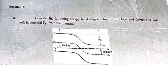
Transcribed Image Text:Question 1:
a.
Consider the following energy band diagram for the junction and determine the
built-in potential Vbt from the diagram
En
E₂
E
0.45 eV
E
0.0.4eV
En
Expert Solution
This question has been solved!
Explore an expertly crafted, step-by-step solution for a thorough understanding of key concepts.

This is a popular solution!

Trending now
This is a popular solution!

Step by step
Solved in 2 steps

Knowledge Booster


Learn more about
Need a deep-dive on the concept behind this application? Look no further. Learn more about this topic, electrical-engineering and related others by exploring similar questions and additional content below.Recommended textbooks for you
Delmar's Standard Textbook Of Electricity
Electrical Engineering
ISBN:
9781337900348
Author:
Stephen L. Herman
Publisher:
Cengage Learning
Delmar's Standard Textbook Of Electricity
Electrical Engineering
ISBN:
9781337900348
Author:
Stephen L. Herman
Publisher:
Cengage Learning