Question 1 Consider using a pair of strain gauges attached on a beam to measure tensile stress that the beam is subject to, as shown in Fig. 1 (a). The measurement system is a bridge circuit consisting of two strain gauges and two fixed resistors as shown in Fig. 1 (b). The supply voltage is V, gauge factor for both gauges is G, the bridge is balanced (R1 = R2, Rg1 = Rg2) when there is no force applied. Rg1 R1 Rg1 (dummy) Vs V R$2 (active) A B Rg2 R2 T Fig. Q1 (a) Fig. Q1 (b) (a) When a small tensile force is applied to the beam, derive the output voltage V, in terms of the given parameters and the strain e.
Question 1 Consider using a pair of strain gauges attached on a beam to measure tensile stress that the beam is subject to, as shown in Fig. 1 (a). The measurement system is a bridge circuit consisting of two strain gauges and two fixed resistors as shown in Fig. 1 (b). The supply voltage is V, gauge factor for both gauges is G, the bridge is balanced (R1 = R2, Rg1 = Rg2) when there is no force applied. Rg1 R1 Rg1 (dummy) Vs V R$2 (active) A B Rg2 R2 T Fig. Q1 (a) Fig. Q1 (b) (a) When a small tensile force is applied to the beam, derive the output voltage V, in terms of the given parameters and the strain e.

Introductory Circuit Analysis (13th Edition)
13th Edition
ISBN:9780133923605
Author:Robert L. Boylestad
Publisher:Robert L. Boylestad
Chapter1: Introduction
Section: Chapter Questions
Problem 1P: Visit your local library (at school or home) and describe the extent to which it provides literature...

Related questions

Question
Help just do A thank you.
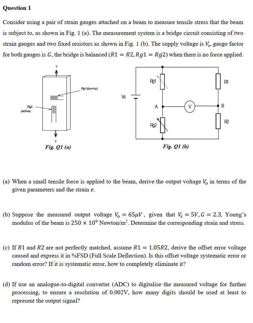
Transcribed Image Text:Question 1
Consider using a pair of strain gauges attached on a beam to measure tensile stress that the beam
is subject to, as shown in Fig. 1 (a). The measurement system is a bridge circuit consisting of two
strain gauges and two fixed resistors as shown in Fig. 1 (b). The supply voltage is V, gauge factor
for both gauges is G, the bridge is balanced (R1 = R2, Rg1 = Rg2) when there is no force applied.
T
Rg1
R1
Pg1 (dummy)
Rg2
(active)
A
B
Rg2
R2
T
Fig. Q1 (a)
Fig. Q1 (b)
(a) When a small tensile force is applied to the beam, derive the output voltage V, in terms of the
given parameters and the strain e.
(b) Suppose the measured output voltage V₁ = 65μV, given that V = 5V, G = 2.3, Young's
modulus of the beam is 250 × 10° Newton/m². Determine the corresponding strain and stress.
(c) If R1 and R2 are not perfectly matched, assume R1 = 1.05R2, derive the offset error voltage
caused and express it in %FSD (Full Scale Deflection). Is this offset voltage systematic error or
random error? If it is systematic error, how to completely eliminate it?
(d) If use an analogue-to-digital converter (ADC) to digitalise the measured voltage for further
processing, to ensure a resolution of 0.002V, how many digits should be used at least to
represent the output signal?
Expert Solution
This question has been solved!
Explore an expertly crafted, step-by-step solution for a thorough understanding of key concepts.

Step by step
Solved in 3 steps with 2 images

Knowledge Booster


Learn more about
Need a deep-dive on the concept behind this application? Look no further. Learn more about this topic, electrical-engineering and related others by exploring similar questions and additional content below.Recommended textbooks for you
Introductory Circuit Analysis (13th Edition)
Electrical Engineering
ISBN:
9780133923605
Author:
Robert L. Boylestad
Publisher:
PEARSON

Delmar's Standard Textbook Of Electricity
Electrical Engineering
ISBN:
9781337900348
Author:
Stephen L. Herman
Publisher:
Cengage Learning

Programmable Logic Controllers
Electrical Engineering
ISBN:
9780073373843
Author:
Frank D. Petruzella
Publisher:
McGraw-Hill Education
Introductory Circuit Analysis (13th Edition)
Electrical Engineering
ISBN:
9780133923605
Author:
Robert L. Boylestad
Publisher:
PEARSON
Delmar's Standard Textbook Of Electricity
Electrical Engineering
ISBN:
9781337900348
Author:
Stephen L. Herman
Publisher:
Cengage Learning
Programmable Logic Controllers
Electrical Engineering
ISBN:
9780073373843
Author:
Frank D. Petruzella
Publisher:
McGraw-Hill Education

Fundamentals of Electric Circuits
Electrical Engineering
ISBN:
9780078028229
Author:
Charles K Alexander, Matthew Sadiku
Publisher:
McGraw-Hill Education

Electric Circuits. (11th Edition)
Electrical Engineering
ISBN:
9780134746968
Author:
James W. Nilsson, Susan Riedel
Publisher:
PEARSON

Engineering Electromagnetics
Electrical Engineering
ISBN:
9780078028151
Author:
Hayt, William H. (william Hart), Jr, BUCK, John A.
Publisher:
Mcgraw-hill Education,