QUESTION 1 Determine the intemal forces at point D for the structure as shown in Figure Q1. 6 kN 3 m B 1 m 3 m A 3 m Figure Q1
QUESTION 1 Determine the intemal forces at point D for the structure as shown in Figure Q1. 6 kN 3 m B 1 m 3 m A 3 m Figure Q1

International Edition---engineering Mechanics: Statics, 4th Edition
4th Edition
ISBN:9781305501607
Author:Andrew Pytel And Jaan Kiusalaas
Publisher:Andrew Pytel And Jaan Kiusalaas
Chapter6: Beams And Cables
Section: Chapter Questions
Problem 6.6P: Find the internal force systems acting on sections 1 and 2.

Related questions
Topic Video
Question
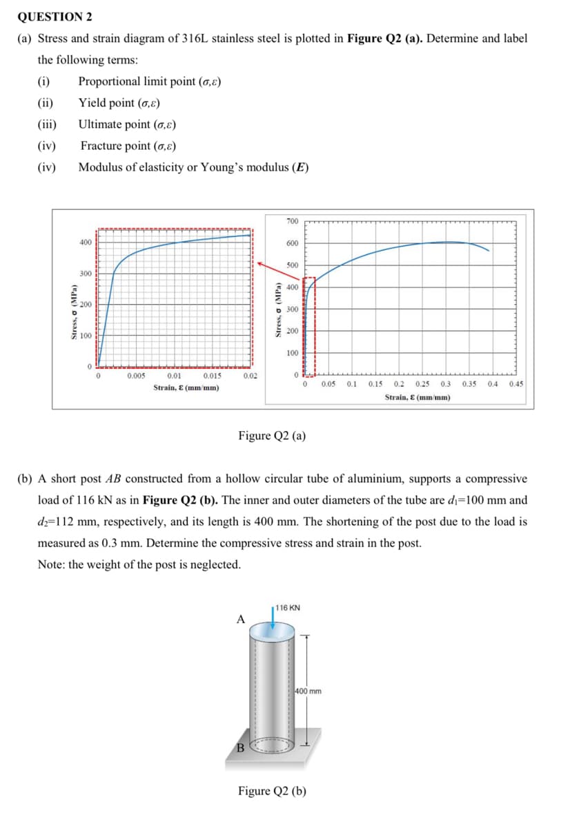
Transcribed Image Text:QUESTION 2
(a) Stress and strain diagram of 316L stainless steel is plotted in Figure Q2 (a). Determine and label
the following terms:
(i)
Proportional limit point (0,ɛ)
(ii)
Yield point (0,ɛ)
(iii)
Ultimate point (0,8)
(iv)
Fracture point (0,8)
(iv)
Modulus of elasticity or Young's modulus (E)
700
400
600
500
300
400
200
6 300
200
E 100
100
0.005
0.01
0.015
0.02
0.05
0.1
0.15
0.2
0.25
0.3
0.35
0.4
0.45
Strain, E (mm/mm)
Strain, E (mm/mm)
Figure Q2 (a)
(b) A short post AB constructed from a hollow circular tube of aluminium, supports a compressive
load of 116 kN as in Figure Q2 (b). The inner and outer diameters of the tube are di=100 mm and
dz=112 mm, respectively, and its length is 400 mm. The shortening of the post due to the load is
measured as 0.3 mm. Determine the compressive stress and strain in the post.
Note: the weight of the post is neglected.
116 KN
A
400 mm
Figure Q2 (b)
Stress, o (MPa)
Stress, a (MPa)
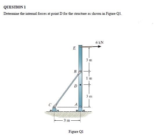
Transcribed Image Text:QUESTION 1
Determine the intemal forces at point D for the structure as shown in Figure Q1.
6 kN
3 m
B
1 m
3 m
A
3 m
Figure Q1
Expert Solution
This question has been solved!
Explore an expertly crafted, step-by-step solution for a thorough understanding of key concepts.

Step by step
Solved in 3 steps with 2 images

Knowledge Booster


Learn more about
Need a deep-dive on the concept behind this application? Look no further. Learn more about this topic, mechanical-engineering and related others by exploring similar questions and additional content below.Recommended textbooks for you
International Edition---engineering Mechanics: St…
Mechanical Engineering
ISBN:
9781305501607
Author:
Andrew Pytel And Jaan Kiusalaas
Publisher:
CENGAGE L
International Edition---engineering Mechanics: St…
Mechanical Engineering
ISBN:
9781305501607
Author:
Andrew Pytel And Jaan Kiusalaas
Publisher:
CENGAGE L