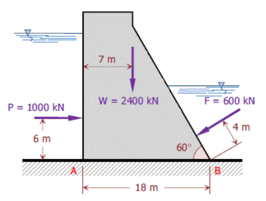
The forces acting on a 1-m length of a dam is shown in the Figure. The upward ground reaction varies uniformly from an intensity of p1 kN/m to p2 kN/m at B. Determine p1, p2, and the horizontal and vertivcal resistance to sliding.


Q: A semicircular flap with a radius r, which can rotate around axis A, closes the outflow from the…
A: Given, Height of the water column , H =1.2 m Radius of the semicircular flap , r = 0.5 m centroid…
Q: A light ball (weight 2.0-g) filled with a very light gas, the ball is connected to a spring as shown…
A:
Q: What would be the maximum weight W of the block, shown in the following figure, so that the tension…
A: The free-body diagram of the provided force system is drawn below. Here, T and W represent the…
Q: What would be the maximum weight W of the block, shown in the following figure, so that the tension…
A: The free-body diagram of the point C is drawn below.
Q: 3.70 The plane rectangular gate can pivot about the support at B. For the conditions given, is it…
A:
Q: The cable shown in Fig. weighs 35 N/m. Determine the maximum tension in the cable and the sag ha in…
A: Determine the central dip by using the below expression.
Q: B. Cords are loop around a small spacer separating two cylinders whose total weight is 375 kg as…
A: Drawing FBD of system with all the forces: Here, N = Normal reaction T1 & T2 = Tensions in…
Q: A steel ball is resting in a trough as shown in the figure. The weight of the ball is 1650 N.…
A: When a given system is in equilibrium, then the net external force acting on the system is equal to…
Q: The uniform crate shown in the figure weighs 200 lb. It is pulled up the incline by a counterweight…
A: The given problem will be solved in following steps: 1.The relation ship between the acceleration of…
Q: What would be the maximum weight W of the block, shown in the following figure, so that the tension…
A:
Q: Based on the following figure and its description, answer Q1, Q2, Q3, Q4 and Q5. Isosceles…
A:
Q: Q2: For the system shown in figure, all chains are of negligible weight, if the tensile force in…
A: Given data: The tension in the chain D is TD=7820 N The acceleration due to gravity is g=10 ms2
Q: 2.0 m 100 kg 2.0 m 0.5 m 1.5m 1.5 m The pulley at E is frictionless. Point B is a pinned connection;…
A:
Q: Q2. Determine all forces acting on body A for the system shown in figure 2. Body A weighs 200 N and…
A:
Q: What would be the maximum weight W of the block, shown in the following figure, so that the tension…
A: Let the tension in string AC be T1 And the tension in string BC be T2 the angle opposite to three…
Q: 2.0m 100 kg 2.0 m 0. 1.5m 1.5m The pulley at E is frictionless. Point B is a pinned connection;…
A:
Q: Three pairs of flexible cables, spaced at 120° inter- vals, are used to stabilize a 1000-ft…
A: Draw free body diagram of cable AC
Q: A 150 lb cylindrical tank is at rest as shown as shown in the figure. Determine the force P required…
A: The free-body diagram of the cylindrical tank is shown below.
Q: Q10/ The steel Cable AB and AC are attached to the top of the transmission tower. The tension force…
A:
Q: What would be the maximum weight W of the block, shown in the following figure, so that the tension…
A: According to the given information, tension developed in a cable does not exceed 500 N. Let us…
Q: A cylindrical liquid storage tank weighing is to be pushed over a change of elevation of 0.25m by a…
A:
Q: Q.1) For the plate shown in figure, determine the forces in three ropes if the plate weighs 1.6 kN.…
A: Determine the position vector along AB, AC and AD.
Q: QJ As shown in figure below, determine the weight of concrete cylinder, for equilibrium the gate AB.…
A: Draw the free body diagram of the gate.
Q: 2m Im 1m -2m 2m 2m The crate weighs 450 kg and is supported by three cables as shown in the figure…
A: As per our guidelines we are supposed to solve 3 sub-parts if multiple sub-parts are asked. Kindly…
Q: Q1. Two masses are suspended by the cable system as shown in Figure Q1. The cable BC is horizontal.…
A:
Q: Cords are looped around a small spacer separating two cylinder each weighing 400kn and pass over a…
A:
Q: 2. Find the distance x (measured along AB) at which a horizontal force of 60 lb should be applied to…
A:
Q: What would be the maximum weight W of the block, shown in the following figure, so that the tension…
A:
Q: What would be the maximum weight W of the block, shown in the following figure, so that the tension…
A:
Q: The block shown in the figure below is acted on by its weight, W = 1300 Lbs, a horizontal force H =…
A:
Q: Ql: A ladder (275N) weight is rest as shown in figure, if the vertical wall is smooth and the…
A:
Q: Q.4) Determine the tensions in the three cables supporting a weight of 180 N as shown in figure…
A: Let us take origin as O. FBD: From figure, O = (0,0,0) A = (4,-8,5) B = (-6,-8,5) C = (0,8,5)…
Q: 35 A ball of weight 120 N rests in a right angled groove as shown in Fig. The sides of the groove…
A:
Q: 2- Find the applied force by the hydraulic cylinder in the truck shown graphically using KS: 1cm=1m,…
A: Given Weight = 25 kN To find Force required to lift the weight
Q: A 12.0 kg weight hangs from a 7.50 m pole as illustrated in the diagram. The pole has a mass of 8.0…
A: Write the given value using suitable variables. Here W signifies given weight, L signifies pole…
Q: (c) A bank of lights of 110 kg is suspended above a movie set by the system of cables as shown in…
A:
Q: 13.) Cords are loop around a small spacer separating two cylinders each weighing 400 lb and pass, as…
A: GIVEN DATA WEIGHT OF CYLINDER W=800lb WE HAVE TO FIND ANGLE AND NORMAL PRESSURE N
Q: Q2. Determine all forces acting on body A for the system shown in figure 2. Body A weighs 200 N and…
A:
Q: Q4//Determine the required vertical force F to be applied at the lower edge to open the square gate…
A: Area= 2.8×2.8 =7.84m2 Location of CG(y) =1.8+2.8sin45/2 =2.78m…
Q: Q: The door is held open by means of two chain. if the tension in AB and CD is FA= 300N and Fc= 250…
A: As per bartleby expert guidelines we are supposed to answer one question.If you want solution of the…
Q: A 3.5m - high . 5m wide rectangular gate is hinged at the top edge at A and is restrained by a fixed…
A: The total area of the rectangular gate is A= 3.5×5=17.5m2 Let ρ be the density of water , ρ=1000kgm3…
Q: m rope which can withstand a maximum tension Fm. For Fm from 40 to 140 N use computation software to…
A: weight of the bag =5 kg pushed off the top of a wall and swings in a vertical plane at the end of…
Q: Perfectly smooth W=240 lb 5' 5' .A 4. 1' C 3.
A: Consider the free body diagram:
Q: Find the rod forces in the truss system, whose dimensions and loading condition are given in the…
A:
Q: The uniform crate shown in the figure weighs 200 lb. It is pulled up the incline by a counterweight…
A: The relation between the displacements of block of weight 'W' and the crate will be determined, and…
Q: A uniform sphere of weight W rests between a smooth vertical plane and a smooth plane at an angle 0…
A:
Q: Three boxes, A, B, and C, are placed on a frictionless surface as shown in the diagram below. B A If…
A:
Q: Y X 36 N 20 kg 4.0 kg
A:
Q: QUESTION 6 A ladder with negligible mass is supporting a 54 kg person as shown in Figure 6. If the…
A: For a step-by-step solution have a look through the attached pictures of the solution. The required…
Q: The uniform crate shown in the figure weighs 200 lb. It pulled up the incline by a counterweight W…
A: The problem has been solved and has been attached. The answers does not match with the given one as…
The forces acting on a 1-m length of a dam is shown in the Figure. The upward ground reaction varies uniformly from an intensity of p1 kN/m to p2 kN/m at B. Determine p1, p2, and the horizontal and vertivcal resistance to sliding.

Step by step
Solved in 2 steps with 2 images

- a. An overhead line has the following data: Span length= 160 m Conductor diameter= 0.95 cm Weight per unit length of the conductor= 0.65 kg/m Ultimate stress= 4,250 kg/cm2 Wind pressure= 40 kg/m2 Safety factor= 5 Calculate the sag? b. Derive the expression for the lowest point of the catenary curve if the supports are at different levels. Given that weight of conductor= 0.35 kg/m. Maximum allowable tension= 800 kg. Span length= 160 m and safety factor = 2. Find minimum point of catenary if supports are at 70 m and 60 m.[Note: Dont attempt this question second time if u have already provided the solution one time ] The stepped shaft in the figure transmits 19.2 kW of power at 180 rpm. Determine the required shaft diameter using the maximum strain energy (Von Mises) hypothesis. Take L=0.8 m, F=6kN, τem=72 MPa, σem= 108 MPa.(Q1) A uniform beam, of mass 31 kg/m run, is simply supported on a span of3.6 m. Taking EI for the beam as 7 MN.m2, calculate the frequency oftransverse vibrations.This frequency is to be reduced by 40% by fixing three equal masses tothe beam, at the mid-point and the quarter points. Calculate how muchthese masses should be. (Q2) A beam 6 m long, simply supported at each end, carries a load of 6 t/mrun, extending from a point 1.2 m from one support to another point 4.2m from the same support. EI for the beam is 110 MN.m2. The mass of thebeam itself may be neglected.Determine the frequency of transverse vibrations of the beam in avertical plane:a) very roughly, assuming the whole load to be concentrated at itscentre of gravity.b) more accurately, by treating the load as three equal concentratedloads applied at suitable points. (Dunkerley's method issuggested.)
- 4 helical springs is used in a suspension system of a motorcycle. The mean coil diameter is 15 cm, spring constant is 40,000 N/m, shear modulus = 80x10^9 N/(m^2), and has 8 effective turns. Determine what must be the wire diameter of the helical spring.Property ASTM A710 Steel AA 7075 Density 7.8 2.81 Yield Strength 585 503 Ultimate Tensile Strength 620 572 Poisson Ratio 0.29 0.33 Shear Modulus 80 26.9 Young’s Modulus 205 71.7 Dimensions Side bar (C-Channel) = 210 x 76 x 6 mm Front Overhang = 935 mm Rear Overhang = 1620 mm Wheel Base = 3800 mm Width = 2250 mm Capacity = 8000 x 9.81 = 78480N Capacity with 1.25% = 98100N Weight of body and engine = 19620N Total load = 117720N Load acting on a single bar of chassis = 58860N Using the information above for two materials Iron (ASTM A710 Steel ) and Aluminum (AA 7075) Calculate for each Material Reaction Force Shear Forces Bending Moment Bending Stress Shear Stress Von Misses Stress Principle Stress Max Shear Stress Total Deflection Draw the Shear Force and bending moment Diagram for each Material. Draw the Equivalent Mohr Circle for each material Conclude with a Comparison of the Deformation of the two Materials.A spherical tank of diameter 1.2 m and wall thickness 50 mm contains compressed air at a pressure of 17 MPa. What is the value of tensile stress? (Assume E = 210 GPa, v = 0.29)
- Given the following properties of bridge deck girder: Barrier Weight, BW = 7.3kN/m Future wearing surface load = 1.20 kPa, Span length, L=12.0 m, Load of stay-in-place metal forms, wsmf=0.335kPa Unit wt of concrete, wc=23.54 kN/m³ Slab thickness = 200mm. •Determine the shear and moment per interior girder due to Dead Load, DC. •Determine the shear and moment per interior girder due to Dead Load, DW.A solid shaft 5 m long is stressed to 60 MPa when twisted through 4 deg . Using G = 83 GPa, what power (Hp) can be transmitted by the shaft at 20 rps?A Hollow power transmission shaft of length ‘L’ 1103 mm, outer diameter ‘D’ 73mm and inner diameter 'd' 50. is required to transmit a power of P 60kW at a speed of 2950rpm. The modulus of rigidity of hardened carbon steel, which the shaft is made of, is 79.5 GPa. Calculate the polar second moment of area of the shaft?
- Shaft length, L and a different allowable maximum shear stress, τmax and subject to a different Torque, T. For steel use a shear modulus, G=81,000 MPa. A steel shaft L meters long is subjected to a torque T. If the shear stress is limited to τmax, calculate: a) The minimum shaft diameter required. b) The angle of twist over the length of the shaft. c) The Power output if your shaft is rotating at 2000 rpm. L= 1.6m, τmax=100MPa , T=1.3kN-mA solid steel shaft 4.5 m long is stressed at 75 MPa when twisted through 4.5°. What power can be transmitted by the shaft at 25 Hz? Use G = 83 GPa.A horizontal shaft AD supported in bearings at A and B and carrying pulleys at C and D is totransmit 75 kW at 500 r.p.m. from drive pulley D to off-take pulley C, Calculate the diameter of shaft. The data given is : P1 = 2 P2 (both horizontal), Q1 = 2 Q2 (bothvertical), radius of pulley C = 220 mm, radius of pulley D = 160 mm, allowable shear stress = 45 MPa.[Ans. 100 mm] Given CD=350mm CA=100mm AB=150mm BD=100mm