Question 1 For the circuit given below, find the value of Ve at steady state condition. + Ve 10 V R40 Ran O A. Vc=3 V O B. Vc=8 V OC.Vc=2 V O D. None of the given answers O E. Vc=6 V OF. Vc 10 V
Question 1 For the circuit given below, find the value of Ve at steady state condition. + Ve 10 V R40 Ran O A. Vc=3 V O B. Vc=8 V OC.Vc=2 V O D. None of the given answers O E. Vc=6 V OF. Vc 10 V

Delmar's Standard Textbook Of Electricity
7th Edition
ISBN:9781337900348
Author:Stephen L. Herman
Publisher:Stephen L. Herman
Chapter18: Resistive-inductive Parallel Circuits
Section: Chapter Questions
Problem 9PP: In an R-L parallel circuit, ET=240 volts, R=560 R = 560 2, and XL=330. Find reactive power.

Related questions
Question
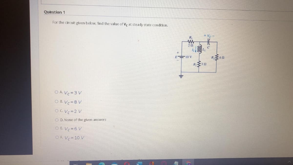
Transcribed Image Text:Question 1
For the circuit given below, find the value of V, at steady state condition.
- A+
20
10 V
R40
R 3n
O A. Vc=3 V
O B. Vc=8 V
OGVC=2 V
O D. None of the given answers
O E. Vc=6 V
O F. Vc= 10 V
Expert Solution
This question has been solved!
Explore an expertly crafted, step-by-step solution for a thorough understanding of key concepts.

This is a popular solution!

Trending now
This is a popular solution!

Step by step
Solved in 2 steps with 2 images

Knowledge Booster


Learn more about
Need a deep-dive on the concept behind this application? Look no further. Learn more about this topic, electrical-engineering and related others by exploring similar questions and additional content below.Recommended textbooks for you
Delmar's Standard Textbook Of Electricity
Electrical Engineering
ISBN:
9781337900348
Author:
Stephen L. Herman
Publisher:
Cengage Learning
Delmar's Standard Textbook Of Electricity
Electrical Engineering
ISBN:
9781337900348
Author:
Stephen L. Herman
Publisher:
Cengage Learning