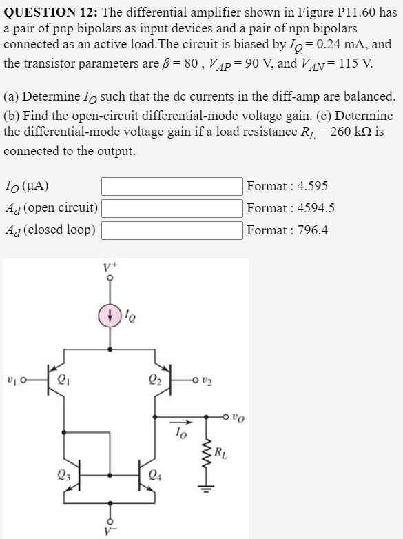
QUESTION 12: The differential amplifier shown in Figure P11.60 has a pair of pnp bipolars as input devices and a pair of npn bipolars connected as an active load.The circuit is biased by Io= 0.24 mA, and the transistor parameters are B = 80 , V4P= 90 V, and VAN= 115 V. (a) Determine Io such that the de currents in the diff-amp are balanced. (b) Find the open-circuit differential-mode voltage gain. (c) Determine the differential-mode voltage gain if a load resistance Rz = 260 k2 is connected to the output. Io (HA) Format : 4.595 Ad (open circuit) Format : 4594.5 Ad (closed loop) Format : 796.4 v+ O v2 Oa lo RL Q3 Q4 V-
QUESTION 12: The differential amplifier shown in Figure P11.60 has a pair of pnp bipolars as input devices and a pair of npn bipolars connected as an active load.The circuit is biased by Io= 0.24 mA, and the transistor parameters are B = 80 , V4P= 90 V, and VAN= 115 V. (a) Determine Io such that the de currents in the diff-amp are balanced. (b) Find the open-circuit differential-mode voltage gain. (c) Determine the differential-mode voltage gain if a load resistance Rz = 260 k2 is connected to the output. Io (HA) Format : 4.595 Ad (open circuit) Format : 4594.5 Ad (closed loop) Format : 796.4 v+ O v2 Oa lo RL Q3 Q4 V-

Introductory Circuit Analysis (13th Edition)
13th Edition
ISBN:9780133923605
Author:Robert L. Boylestad
Publisher:Robert L. Boylestad
Chapter1: Introduction
Section: Chapter Questions
Problem 1P: Visit your local library (at school or home) and describe the extent to which it provides literature...

Related questions
Question
100%
Transcribed Image Text:QUESTION 12: The differential amplifier shown in Figure P11.60 has
a pair of pnp bipolars as input devices and a pair of npn bipolars
connected as an active load. The circuit is biased by Io=0.24 mA, and
the transistor parameters are ß = 80 , VẬP=90 V, and VAN = 115 V.
(a) Determine Io such that the de currents in the diff-amp are balanced.
(b) Find the open-circuit differential-mode voltage gain. (c) Determine
the differential-mode voltage gain if a load resistance R1 = 260 k2 is
connected to the output.
Io (HA)
Format : 4.595
Ad (open circuit)
Format : 4594.5
Ag (closed loop)
Format : 796.4
V+
Q2
Oa 어
RL
Q3
Q4
V-
Expert Solution
This question has been solved!
Explore an expertly crafted, step-by-step solution for a thorough understanding of key concepts.

This is a popular solution!

Trending now
This is a popular solution!

Step by step
Solved in 2 steps with 1 images

Knowledge Booster


Learn more about
Need a deep-dive on the concept behind this application? Look no further. Learn more about this topic, electrical-engineering and related others by exploring similar questions and additional content below.Recommended textbooks for you
Introductory Circuit Analysis (13th Edition)
Electrical Engineering
ISBN:
9780133923605
Author:
Robert L. Boylestad
Publisher:
PEARSON

Delmar's Standard Textbook Of Electricity
Electrical Engineering
ISBN:
9781337900348
Author:
Stephen L. Herman
Publisher:
Cengage Learning

Programmable Logic Controllers
Electrical Engineering
ISBN:
9780073373843
Author:
Frank D. Petruzella
Publisher:
McGraw-Hill Education
Introductory Circuit Analysis (13th Edition)
Electrical Engineering
ISBN:
9780133923605
Author:
Robert L. Boylestad
Publisher:
PEARSON
Delmar's Standard Textbook Of Electricity
Electrical Engineering
ISBN:
9781337900348
Author:
Stephen L. Herman
Publisher:
Cengage Learning
Programmable Logic Controllers
Electrical Engineering
ISBN:
9780073373843
Author:
Frank D. Petruzella
Publisher:
McGraw-Hill Education

Fundamentals of Electric Circuits
Electrical Engineering
ISBN:
9780078028229
Author:
Charles K Alexander, Matthew Sadiku
Publisher:
McGraw-Hill Education

Electric Circuits. (11th Edition)
Electrical Engineering
ISBN:
9780134746968
Author:
James W. Nilsson, Susan Riedel
Publisher:
PEARSON

Engineering Electromagnetics
Electrical Engineering
ISBN:
9780078028151
Author:
Hayt, William H. (william Hart), Jr, BUCK, John A.
Publisher:
Mcgraw-hill Education,