Question 2 The op amp has v₁ = -0.1 V, a random input offset voltage, Vos ≤ 10 mV and input bias currents, IBI IB2 10 μA. R₁ = 5 ks, R2 = 10 k2 and R3 = 2 k. Find the maximum possible positive output voltage, vo. Vi R₁ R₂ Vo Final Answer Vo= (V)
Question 2 The op amp has v₁ = -0.1 V, a random input offset voltage, Vos ≤ 10 mV and input bias currents, IBI IB2 10 μA. R₁ = 5 ks, R2 = 10 k2 and R3 = 2 k. Find the maximum possible positive output voltage, vo. Vi R₁ R₂ Vo Final Answer Vo= (V)

Delmar's Standard Textbook Of Electricity
7th Edition
ISBN:9781337900348
Author:Stephen L. Herman
Publisher:Stephen L. Herman
Chapter18: Resistive-inductive Parallel Circuits
Section: Chapter Questions
Problem 13PP: In an R-L parallel circuit, IT=1.25 amps, R=1.2k, and XL=1k. Find IR

Related questions
Question
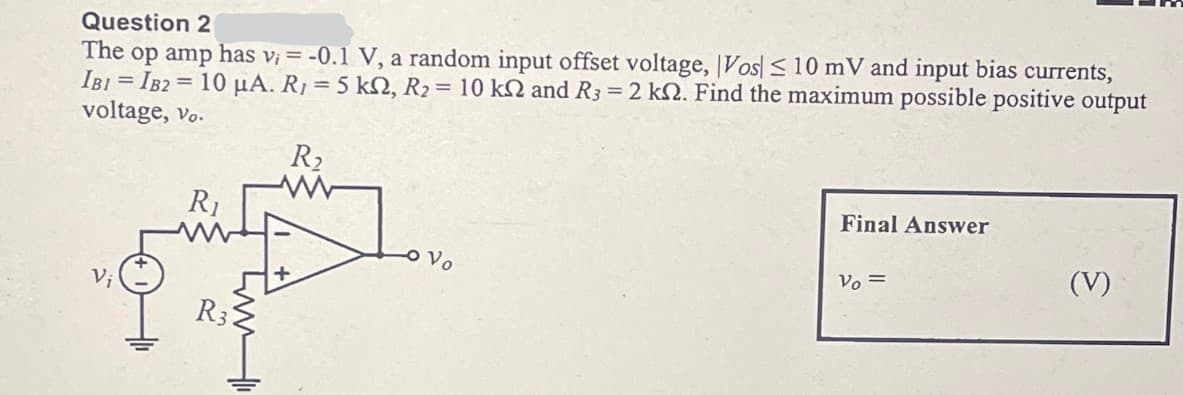
Transcribed Image Text:Question 2
The op amp has v₁ = -0.1 V, a random input offset voltage, Vos ≤ 10 mV and input bias currents,
IBI IB2 10 μA. R₁ = 5 ks, R2 = 10 k2 and R3 = 2 k. Find the maximum possible positive output
voltage, vo.
Vi
R₁
R₂
Vo
Final Answer
Vo=
(V)
Expert Solution
This question has been solved!
Explore an expertly crafted, step-by-step solution for a thorough understanding of key concepts.

Step by step
Solved in 2 steps with 1 images

Recommended textbooks for you
Delmar's Standard Textbook Of Electricity
Electrical Engineering
ISBN:
9781337900348
Author:
Stephen L. Herman
Publisher:
Cengage Learning
Delmar's Standard Textbook Of Electricity
Electrical Engineering
ISBN:
9781337900348
Author:
Stephen L. Herman
Publisher:
Cengage Learning