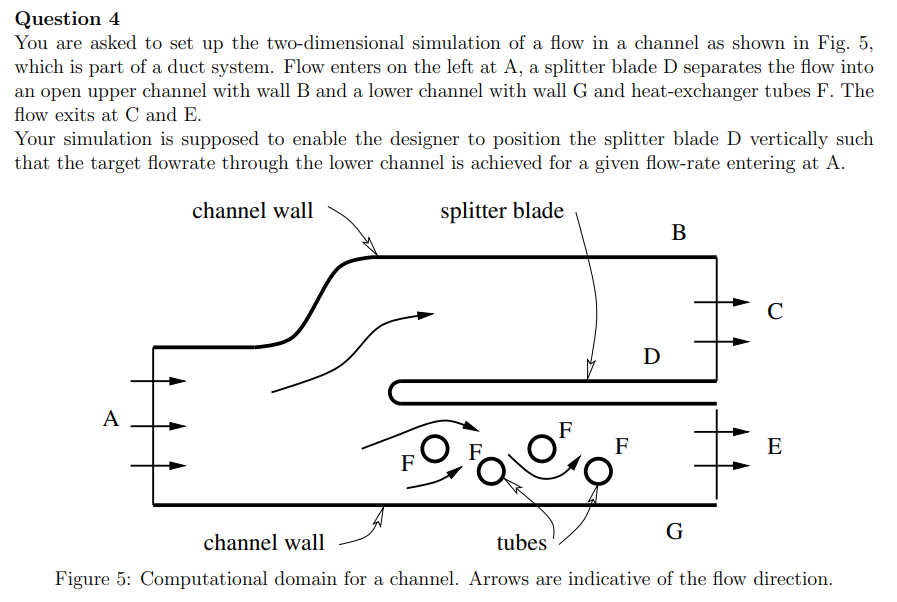
Question 4 You are asked to set up the two-dimensional simulation of a flow in a channel as shown in Fig. 5, which is part of a duct system. Flow enters on the left at A, a splitter blade D separates the flow into an open upper channel with wall B and a lower channel with wall G and heat-exchanger tubes F. The flow exits at C and E. Your simulation is supposed to enable the designer to position the splitter blade D vertically such that the target flowrate through the lower channel is achieved for a given flow-rate entering at A.


Im finding it difficult to answer this question, can you help in finding a solution?:
a) Choose boundary conditions (b.c.) for the boundaries A-G from the types of b.c. typically implemented with an incompressible CFD solver. State what quantities those b.c. impose, and which they leave undefined. Justify your choice of boundary condition.
b) Discuss the most important errors your choice of b.c. may introduce and how those could be remedied.
c) While walking past your desk, your team-leader reminds you that the quantity of interest is the massflow in the lower channel, and proposes to use a slip-wall condition for B. Unfortunately she doesn’t explain her reasoning. For the next team meeting, prepare a discussion of the pros and cons of that suggestion, and explain whether or not you think this suggestion should be followed.

Step by step
Solved in 3 steps with 4 images


