Question I 
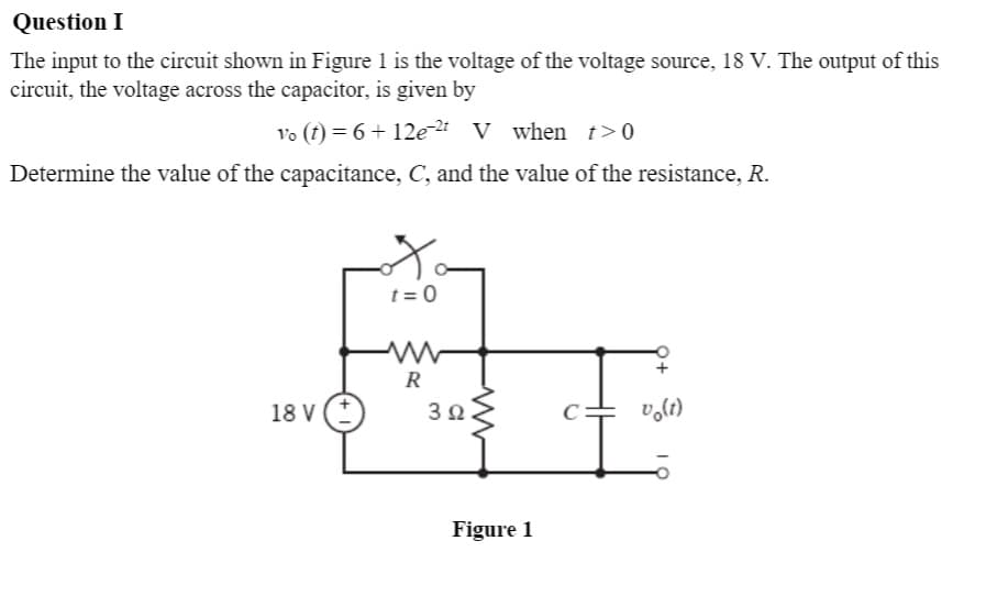
The input to the circuit shown in Figure 1 is the voltage of the voltage source, 18 V. The output of this circuit, the voltage across the capacitor, is given by vo (t) = 6 + 12e-2 V when t>0 Determine the value of the capacitance, C, and the value of the resistance, R. t = 0 R 18 V 3Ω. Figure 1
Q: V = 75cos(5000t)V L1 110mH, L2 = 4mHe C, = 4µF %3D %3D C1 L2 ll Ix R1 V1 Vo 10 Q 100 Ix ll
A: The solution is given below
Q: An uncharged 0.2 μF capacitor is driven by a triangular current pulse. The current pulse is…
A: Write the expression for the current at different intervals.
Q: Problem 4 In the given circuit, the switch has been in position A for a long time and switches to…
A:
Q: 1. The capacitor in the figure is charged with vc (0) = 10 V. Find the mathematical expressions for…
A: Here we discuss about the procedure of the transient analysis of RC circuit.
Q: 3. A resistor and a capacitor are connected in series with a variable inductor. When the circuit is…
A:
Q: Consider the circuit shown in the figure, with C, = 6.42 µF and C, = 7.44 µF. %3D 6.00 µF 2.00 µF C2…
A: Given DATA
Q: The current flowing through a 1.6 mF capacitor is shown in the figure below. Assume the passive sign…
A: In this question, Find the voltage across the capacitor at time to= 200ms, 600ms and 1.2s.…
Q: Find the equivalent capacitance with respect to the terminals a, b for the circuit shown The…
A: The equivalent capacitance across terminals a and b is obtained by following the below procedure,
Q: Q8. Explain briefly the application / use of Capacitor 1 and Capacitor 2 in the Page circuit shown…
A: Capacitor 1 is called as the coupling capacitor which is used to send the input to the base of…
Q: a. Calculate the value of R that will make the initial energy stored in the capacitor the same as…
A: We will find out resistance value for given Condition and current and voltage for given circuit .
Q: For the circuit shown Figure 3, Calculate the expression of the Ve(t) assume the initial value of…
A:
Q: A 200µF capacitor is connected in series to a 250V, 60Hz source. Assuming its resistance is 20Ω,…
A:
Q: Determine the inductor current i(t) for both t = 0– and t > 0 for the given circuit. Assume V = 27…
A: Before t=0, steady state was reached so inductor acts as a short circuit and switch is open.…
Q: Q3 The voltage across an inductor with inductance of 510 mH is given by t, 0st<1 VL(t) = 1, 1<t<3 V…
A:
Q: For the circuit of figure below, determine i(f), v¿(t), v(f), the energy stored in the capacitance,…
A: Write the expression for the current in the circuit.…
Q: The circuit elements in the circuit L=50 mH, and C=0.2 μF. The initial inductor current is−45 mA and…
A: From the given circuit the initial inductor current is −45 mA and the initial capacitor voltage is…
Q: 1. For the circuit shown below, if the maximum deflection is 0.4 and it was 0.2 for a reference…
A: The circuit diagram is: When the switch is at position “a” the capacitors are charged and when the…
Q: 4. If the current flowing through a 75 mH inductor has the waveform shown in figure 3, (a)sketch the…
A:
Q: The circuit elements in the circuit L=50 mH, and C=0.2 μF. The initial inductor current is−45 mA and…
A: Let us examine the behavior of circuit elements at t=0
Q: For the circuit shown Figure 3, Calculate the expression of the Ve(t) assume the initial value of…
A: for the above-given circuit expression of Vc(t) is calculated as shown below
Q: 2µF A 6)Three capacitors are connected as shown in the figure (assume 3 significant figs.) 4µF 6µF B…
A: Here three capacitance given and we need to find equivalent capacitance between points A and B
Q: df Find the expression for the voltage and current of both the capacitor and the inductor as a…
A:
Q: Problem 2. Calculate the capacitor voltage, v, for t> 0 for the given circuit, assume and initial…
A: The given circuit is shown below. The initial capacitor voltage is given 7 Volts. Here the switch…
Q: Under de condition, find i, v,, the energy stored by the inductor and capacitor, for the given…
A: Capacitor is a passive device that store energy in electric field. The energy stored by capacitor is…
Q: Determine v.(f) for t>0. Let i, 10 u(t) HA and assume that the capacitor is initially uncharged. 10…
A: Converting all the element parameters in s-domain, is=10ut μA↔10×10-6s=105s,2 μA↔1s×2…
Q: If the current flowing through a 75 mH inductor has the waveform shown in figure 3, (a)sketch the…
A: In this question, We need to determine the voltage waveform if current waveform is given in the…
Q: 4. If the current flowing through a 75 mH inductor has the waveform shown in figure 3, (a)sketch the…
A: First write the expression for inductor current using slope equation. Now using inductor voltage…
Q: Find the current i(t) for the given circuit when u(t) = 5t, L = 1mH, R = 10k(Ohms), C = 1mF and the…
A: Current through inductor using Laplace Transform:
Q: 6. Obtain the energy stored in each capacitor in the figure as shown under dc conditions. 2 mF 2 k2…
A: Here, we have given a electrical network. This network consists of series and parallel combination…
Q: An inductance of 1 H, a resistance of 400 S2 and capacitance of 5 x 10º F are connected in series…
A: First we will find out total impedance in polar form then we will find out the current we
Q: At time t = 0 s, there is no current following through the inductor in the circuit below. Given Is =…
A: Apply KCL at node and write the equation defining inductor current. Now using diffrential…
Q: The current in a 20 mH inductor is known to be i=40 mA,t≤0; i=A1e−10,000t+A2e−40.000tA,t≥0. The…
A: (a) According to the question, The current through the inductor is it=40 mA…
Q: The 0.1μF capacitor in the circuit shown is charged to 100 V. Att=0 the capacitor is discharged…
A: After the switch is closed the circuit is given as The current in the inductor is given as
Q: 50u(t) V 50 V 6n 2 3 H Discussion: 1- Find the initial and forcing inductance current from your…
A:
Q: Problem #1: If the current flowing through a 75mH inductor has the waveform shown below, (a)…
A: Using slope equation calculate expression for inductor current. Voltage across inductor = Ldi/dt.
Q: Given a set of capacitors: 7 nF, 6 nF, 5 nF, 4 µF, 3 pF and 10 µF, solve the following problems: a.…
A:
Q: 2. For the circuit shown in Fig.1 determine (a) total capacitance (b) total energy in the circuit…
A: A capacitor is an electrical component used to store electrical energy in the form of charge. It…
Q: 1. A parallel plate capacitor with air between the plates has a capacitance of 9 pF. The separation…
A:
Q: 1. The switch in the following circuit closes at t = 0 (assume no initial charge on the capacitor).…
A:
Q: The area of parallel plates capacitor is given by A= (C x d) / (ɛr x ɛ0 ) where, C = capacitance of…
A: From the parallel plate capacitor...
Q: The area of parallel plates capacitor is given by A= (ɛr x ɛ0 x C)/d where, C = capacitance of…
A: We know that capacitance of a parallel plate is C= (eoerA)/d.
Q: Q4/ For the circuit shown, the switch S is at position 2 for a long time, then it change to position…
A:
Q: Theoretically calculate the voltage across the capacitor in the circuit of Figure 1 when t = 0 s, 5…
A:
Q: (c) The voltage, v, across an inductor L, in an electrical circuit drops Exponentially over time, t.…
A:
Q: 2. For the circuit shown in Fig.1 determine (a) total capacitance (b) total energy in the circuit…
A:
Q: For the circuit shown in the following figure, if L= 28 H, Vo=13 V, and R= 28 Q, answer the…
A: In the circuit given data is- L=28 HV∘=13 VR=28 Ω In Laplace domain-…
Q: Question 1 C= 2nF C= 3nF C,= 6nF C,= 4nF C- SnF V= 24V C= 2nF C= 2nF Using the given circuit,…
A:
Q: Q3: For the circuit shown Figure 3, Calculate the expression of the Ve(t) assume the initial value…
A:
Q: Problem 2 Find the expression for the v(t) and current i(t) of of the capacitor as a function of…
A: Here the system is step response, The voltage across the capacitor is given by, vt=Vs+V0-Vse-tτ…
Step by step
Solved in 2 steps with 1 images
- Assume that the current flow through the resistor, IR, is 15 A; the current flow through the inductor, IL is 36 A; and the circuit has an apparent power of 10,803 VA. The frequency of the AC voltage is 60 Hz. ET ER EL IT IR15A IL36A Z R XL VA10,803 P VARSL PF LDesign a single circuit element containing one inductor, one capacitor and one resistor with v(t)=4+2e-3tV and i(t)=2+3e-3tA for t>0. Also specify the value of the inductance, capacitance and the resistance of the three elements.The current in a 20 mH inductor is known to be i=40 mA,t≤0; i=A1e−10,000t+A2e−40.000tA,t≥0. The voltage across the inductor (passive sign convention) is 28 V at t=0. 1. Find the expression for the voltage across the inductor for t>0. 2. Find the time, greater than zero, when the power at the terminals of the inductor is zero.
- A 60 μF capacitor is connected in series with 40 kΩ resistor across a 120 V supply. Determine (a) the time constant, (b) the current when t = 1.5 mS, (c) the current when t = 5 τ,(d) the voltage at the resistor when t = 1.5 mS, (e) the voltage at the capacitor when t = 1.5 mS, and (f) the time required when VR is equal to VC.A 100-pF capacitor is constructed of parallel plates of metal, each having a width W anda length L. The plates are separated by air with a distance d. Assume that L and W are bothmuch larger than d. What is the new capacitance ifa. both L and W are doubled and the other parameters are unchanged?b. the separation d is doubled and the other parameters are unchanged from their initialvalues? c. the air dielectric is replaced with oil having a relative dielectric constant of 25 and theother parameters are unchanged from their initial values ?For the circuit shown, calculate 1. the initial energy stored in the capacitors; 2. the final energy stored in the capacitors; 3. the total energy delivered to the black box; 4. the percentage of the initial energy stored that is delivered to the black box; and 5. the time, in milliseconds, it takes to deliver 7.5 mJ to the black box.
- Can you please help with this question? The triangular voltage pulse shown below is applied to a 200 mF capacitor. a) Write the expressions thatdescribe vc(t) in the five time intervals t < 0, 0 ≤ t ≤ 2 , 2 ≤ t ≤ 6, 6 ≤ t ≤ 8, and t > 8. b) Derive theexpressions for the capacitor current, power, and energy for the time intervals in part (a).A 20.0 μF capacitor, 25.0 μF capacitor, and a 50.0 μF capacitor areconnected in parallel to a 24.0 V battery. a) What is the equivalent capacitance of the combination?b) What is the charge on each capacitor?c) What is the potential difference across each capacitor?d) What is the energy stored in each capacitor?e) What is the total energy stored?Fill in the blanksadd, capacitance, charge capacity, dielectric, dissipate, electrical circuits, , passive, plates,proximity, storesA capacitor is a 1 …………. two-terminal electrical component that 2 ……… potential energy in anelectric field. The effect of a capacitor is known as 3. …………... While some capacitance exists betweenany two electrical conductors in 4. …………… in a circuit, a capacitor is a component designed to 5.…… capacitance to a circuit. The capacitor was originally known as a condenser.The physical form and construction of practical capacitors vary widely and many capacitor types are incommon use. Most capacitors contain at least two electrical conductors often in the form of metallic 6.………… or surfaces separated by a 7. ………medium. A conductor may be a foil, thin film, or anelectrolyte. The nonconducting dielectric acts to increase the capacitor's 8. ………… ………. Materialscommonly used as dielectrics include glass, ceramic, plastic film, paper, mica, and oxide…
- A 811 uF capacitor has an initial voltage, v(0) = 1 V. If the current flowing through the capacitor is i(t) = 18 mA, what is the voltage v(t) across the capacitor, at time t= 12ms? Enter your answer to 3 significant figures.Design a single circuit element containing one inductor, one capacitor and one resistor with v(t)=-3e-3tV and i(t)=4+2e-3tA for t>0. Also specify the value of the inductance, capacitance and the resistance of the three element.The circuit shown in the attached image contains a voltage source with emf ε = 2.99 V, a resistor with resistance R = 135 kΩ, and a capacitor with capacitance C = 612 nF. When switch S is set to position a, the three circuit elements are in series. When the switch is in position b, the battery is excluded from the circuit. The switch is initially moved to position a, where it remains for a sufficiently long time that the capacitor is fully charged. The switch is now moved to position b. What is the magnitude of the instantaneous current, in amperes, through the resistor the instant the switch makes contact with terminal b? With time meausred the instant that switch S is closed in position b, calculate the time, in seconds, when the charge on the capacitor is one-half of its maximum value. Calculate the current through the resistor, in amperes, at time t = 155.5 ms after the switch is closed in position b.