1. The capacitor in the figure is charged with vc (0) = 10 V. Find the mathematical expressions for vc (t) and ix (t) for all time t > 0. 20 μF 2 kn 6 kn t=0,2s 2 k M+10 V +10 Vo VC
Q: 36V (b) Find v1 v2 v3 v4 1502 V₁ 4023 V₂ Va ww 50 792
A:
Q: Q4 a) Determine the suitable capacitor to make 90° electrical between Im and la at starting running…
A: Types of single induction motor Capacitor start IM Permanent split capacitor Wound Rotor Two valve…
Q: Q/ Analyze the circuit using Nodel's theorem ? 202 4 A 4.5 2.52 1) 8 A
A:
Q: Find t 0.5 ms 40 Ω Μ 8 Ω 160 Ω 20 mH Μ
A:
Q: Design a circuit to bias the MOSFET in figure shown, so that its drain current is 5 μA. Estimate…
A: MOSFET is the metal oxide semiconductor field effect transistor. It allow the flow of current in a…
Q: R H1 H2 G3 G2 H3 G1 H4 с
A: Transfer function:- It is provide relationship between input and output. Transfer function is a…
Q: a: considering the unity feedback system of fig. ,prove the settling time of the resulting second…
A:
Q: By using decoder, design a logic circuit to that can be used as code converter which translate Ex-3…
A: To design a logic circuit to translate Ex-3 code to 8-4-2-1 code
Q: 14. The operational amplifier circuit shown in the following figure includes a thermistor. V+ 100 (2…
A: Since you have asked multiple questions, we will solve the first question for you. If you want any…
Q: Design a 3-Bit (fixed reference) comparator for 100 reference values. b) Logic Gates c) PROM d)…
A: LOGIC GATES: A logic gate is a device that acts as a building block They perform basic logical…
Q: 7. What is the purpose of this circuit below,- FUSE 1A 4x114001 3 1 . Write the name and function…
A: The full wave rectifier circuit is made-up of 4 standard diodes, which are connected in a…
Q: Estimate the relative error in measuring the unknown resistor when are using the Ammeter- Voltmeter…
A: Ammeter Voltmeter Method- The instruments required for this test are usually available in the…
Q: Example 5.3 Calculate the cut-off or "breakpoint" frequency (fe) for a simple passive high pass…
A:
Q: A transformer takes a current of 0.8A when its primary is connected to a 240 volt, 50 Hzsupply, the…
A: Given data : No-load current io=0.8A Supply voltage Vo=240V Open circuit loss Po=72W
Q: SECTION 13.2 Sinusoidal ac Voltage Characteristics and Definitions 1. For the periodic waveform of…
A: The given waveform is a periodic waveform and the required parameters can be calculated based on the…
Q: Calculate the current drawn from a 50 V, 60Hz supply by an 80 mH inductor? O 1.66kA O 1.66A O 166A O…
A: Given, Voltage, Vs = 50 V Frequency, f = 60 Hz Inductance, L = 80 mH
Q: 68 k 20 k Q-point for the circuit below is IDQ = 5.4 mA VGSQ = 2.4 V -20V T'o 2.7 k12 D Vps 1.8k…
A: Q point is the bias point. It also known as the operating point of a device. In Q- point Dc voltage…
Q: During a specific time segment of the day, a remote producer has surplus power and a load center…
A: Electrical power system has three stages, generation, transmission and distribution. All the three…
Q: Find the equivalent resistance Rab for each of the circuits in Fig. P3.6.
A:
Q: Question By using decoder, design a logic circuit to that can be used as code converter which…
A:
Q: A // water treatment plant is used to process 30000 m²/d. The rapid mixing tank is to have a…
A: Given data, The Volume of the tank is 30000 m3/d Detention time is 1 min The value of the G is…
Q: 21) For the circuit shown in fig.(*), find the average power consumed n the 2 2 resistor if: v(t) =…
A: Given circuit with Voltage and current source v(t) and i(t) with harmonics.
Q: Apply Thevenin's theorem to determine the current I through the resistance 3KQ for the circuit in…
A:
Q: Consider the circuit on the left with two resistors, a capacitor and an ideal OP-AMP. You may make…
A: The Given Ideal OP-AMP circuit is
Q: 16. A billion electrons pass through a cross- section of a conductor in 10-³s. The current S. is (1)…
A: Given, Number of electrons, n = 109 Charge on electron, e=1.6×10⁻¹⁹ C Time, t = 10-3 s
Q: Explain in paragraph the relationships of resistance, voltage and current, and the distribution of…
A:
Q: Find the Thévenin equivalent circuit for the network in the shaded area of the network of figure…
A:
Q: Q.IA. Two region consist of: (1)Region one z>0 consist of dielectric medium (cr-4) (2)Region two z<0…
A: Given data, There are two regions, 1) z>0 is dielectric medium(εr = 4). 2)z<0 is the perfect…
Q: A single phase transformer is given: SN= = 100 kVA, V₁10 kV t = 25. The short circuit parameters…
A:
Q: And dī= dpā p+ pd ØaØ+dzāz 4 dp ..vab=₁(P)dp Pl_)dp=-2² √10 p 10 2TEOP BAIX ρι PL Inplio In :: vab…
A: In Vab equation ln(10/4) is getting as given below
Q: Find the unit-impulse response for each of the following linear systems. a. y(n) = 0.5x(n) – 0.5x(n…
A: Given: Unit-impulse response is required for the given linear systems.
Q: B. In cylindrical conductor of radius 2 mm, the current density varies with distance from the axis…
A:
Q: What is the value of the output voltage for the 311 comparator circuit shown below if the input…
A: Operational amplifier is a analog circuit it takes differential voltage as input and gives the a…
Q: 18. How long does it take 50 µC of charge to pass a point in a circuit if the current flow is 15 mA?…
A: Given, Charge, q=50 μC=50×10-6 C Current flow, i=15 mA=15×10-3 A
Q: 3- (A)16 4- By Boolean Algebra YZ + (X + Z) + (XY+XZ) = Z + X. 5- OR gate produce 1 out puts when…
A: According to bartleby question answer rule I have to solve one question because all are different…
Q: r the Circuit in Fig. 1, find the Thevenin and Norton equivalent circuits at terminals a-b 18 V 10Ω…
A:
Q: A 12-stage impulse voltage generator has a capacitor C. The wave front resistance equal to 0.6kΩ and…
A: n= 12 Wave front resistance, R1 =0.6 kilo-ohm = 600 ohm Wave tail resistance, R2 =7019 ohm Wave…
Q: Τ ~ em 3772 P(me) R₁ (@-@rm)
A: Induction motor: It works on the induction principle. It is single-side exciting and runs less than…
Q: 23. Two resistors (110 Q, 115 ) are connected in parallel with a 220-V supply. What is the total…
A:
Q: The ACSR conductor Falcon is used in a 3-phase equidistant configuration with D = 25 feet. The per…
A: Given data : distance D=25 feet
Q: What are the factors affecting the dielectric strength of Transformer oil?? Explain the maintenance…
A: Given Questions on transformer oil. Please find the answers below.
Q: d) 1.3 A parallel plate capacitor of plate area 20 cm² and plate separation of 4 mm is connected to…
A: The capacitor of the parallel plate capacitor for the initial configuration is, Ci=ε0AdA=20 cm2d=4…
Q: 1. Using KCL, write the write the expression ²3↑ V3 a V4 + Vs Is Vs+ V1_ is 16 d 2. Using KVL. Write…
A:
Q: 1. Determine the average and rms values of the following 2 waveforms. In the first figure the…
A: RMS alternative current value is greater than the average value. RMS value of sine wave is determine…
Q: Q/Determine the output Signal of the Circuit of Fig 1 with Component : Rf = 200ks, R₁ = 5K²²…
A: Given data : Feedback resistance RF=200kΩ And other resistance R1=5kΩ , R2=2.5kΩR3=100kΩ…
Q: EX2: infinite line along the z-axis with 20 nc/m. Calculate the capacitance between p=10 and p=4 for…
A: Used first Maxwell's equation. Dot product of E(electric field) and top, bottom surfaces are equals…
Q: For the current-divider circuit in Fig. P3.19 calcula - a) i, and vo. b) the power dissipated in the…
A: In this question we will find unknown current, voltage and power consumed in 6 ohm resistor and…
Q: The magnetic field intensity is given in square region 0.5<x< 1 y=0, LC2(15 by H = ² ax + x³ ay + y²…
A: For the above given question we need to calculate the value of given line integral over the given…
Q: Find the voltage Vout and the current I in the circuit shown in Figure 5. You can assume that the…
A:
Q: Maxwell's equations for harmonic waves are a. time dependent and space independent ➡. space…
A: An harmonic wave is a wave whose frequency is the multiple of the fundamental frequency provided the…
Please explain procedure
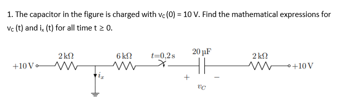
Step by step
Solved in 2 steps
- Fill in all the missing values. Refer to the formulas that follow. Resistance Capacitance Time constant Total time 150 k 100 F 350 k 35 s 350 pF 10 s 0.05 F 1.2 M 0.47 F 12F 0.05 s 86 k 1.5 s 120 k 470 pF 250 nF 100 ms 8 F 150 s 100 k 150 ms 33 k 4 F =RCR=CC=R Totaltime=5Assume that the current flow through the resistor, IR, is 15 A; the current flow through the inductor, IL is 36 A; and the circuit has an apparent power of 10,803 VA. The frequency of the AC voltage is 60 Hz. ET ER EL IT IR15A IL36A Z R XL VA10,803 P VARSL PF LThree capacitors having capacitance values of 20F,40F, and 50F are connected in parallel to a 60 - Hz power line. An ammeter indicates a circuit current of 8.6 amperes. How much current is flowing through the 40F capacitor?
- In this circuit, the capacitance of the capacitor is 1 F, the resistance of the resistor is 1 Ohm, and the battery voltage = 1 V. When the switch is moved from a to b at time t=0, the amount of electric charge stored in the capacitor at t=1 second is approx.. .C.A 60 μF capacitor is connected in series with 40 kΩ resistor across a 120 V supply. Determine (a) the time constant, (b) the current when t = 1.5 mS, (c) the current when t = 5 τ,(d) the voltage at the resistor when t = 1.5 mS, (e) the voltage at the capacitor when t = 1.5 mS, and (f) the time required when VR is equal to VC.Design a single circuit element containing one inductor, one capacitor and one resistor with v(t)=4+2e-3tV and i(t)=2+3e-3tA for t>0. Also specify the value of the inductance, capacitance and the resistance of the three elements.
- The current in the capacitor is 0 for t<0 and 3 cos 50,000t A for t≥0. Find (a) v(t); (b) the maximum power delivered to the capacitor at any one instant of time; and (c) the maximum energy stored in the capacitor at any one instant of time.A 100-pF capacitor is constructed of parallel plates of metal, each having a width W anda length L. The plates are separated by air with a distance d. Assume that L and W are bothmuch larger than d. What is the new capacitance ifa. both L and W are doubled and the other parameters are unchanged?b. the separation d is doubled and the other parameters are unchanged from their initialvalues? c. the air dielectric is replaced with oil having a relative dielectric constant of 25 and theother parameters are unchanged from their initial values ?2. Suppose you want a capacitor bank with a total capacitance of 0.750 F and you possess numerous 1.50 mF capacitors. What is the smallest number you could hook together to achieve your goal, and how would you connect them?
- The circuit shown in the attached image contains a voltage source with emf ε = 2.99 V, a resistor with resistance R = 135 kΩ, and a capacitor with capacitance C = 612 nF. When switch S is set to position a, the three circuit elements are in series. When the switch is in position b, the battery is excluded from the circuit. The switch is initially moved to position a, where it remains for a sufficiently long time that the capacitor is fully charged. The switch is now moved to position b. What is the magnitude of the instantaneous current, in amperes, through the resistor the instant the switch makes contact with terminal b? With time meausred the instant that switch S is closed in position b, calculate the time, in seconds, when the charge on the capacitor is one-half of its maximum value. Calculate the current through the resistor, in amperes, at time t = 155.5 ms after the switch is closed in position b.A 767 uF capacitor has an initial voltage, v(0) = 2 V. If the current flowing through the capacitor is i(t) = 11 mA, what is the voltage v(t) across the capacitor, at time t= 40ms? Enter your answer to 3 significant figures.All capacitors were initially discharged. at t = 0, S1 is placed at position 1 and S2 is closed. Calculate the Thevenin-equivalent voltage seen by the equivalent capacitor during this phase. Enter your answer in V rounded to 2 decimal places. At t = 15 ms, S1 is placed at position 2 and S2 is kept closed. At t = 25 ms, S1 is kept at position 2 and S2 is opened. Data: V1 = 20 V; R1 = 8.0 kΩ, R2 = 10 kΩ, R3 = 2.5 kΩ, R4 = 3 kΩ, R5 = 16 kΩ, R6 = 10.5 kΩ; C1 = 3.5 µF, C2 = 7.0 µF, C3 = 13 µF