Question 
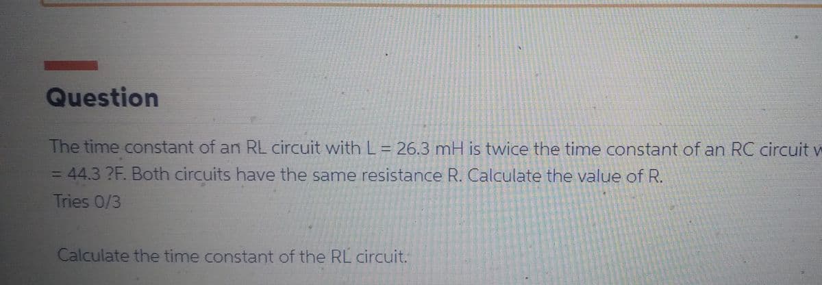
The time constant of an RL circuit with L = 26.3 mH is twice the time constant of an RC circul = 44.3 ?F. Both circuits have the same resistance R. Calculate the value of R. Tries 0/3 Calculate the time constant of the RL circuit.
Q: A device has an output bit rate of 512 kbits/s. Design a digital modulation scheme for the device if…
A: According to the question, we need to design a digital modulation scheme for which Bit rate=512 k…
Q: Calculate the voltage across resistance R3. R₁ ww 10V + 2V + ले । ww 3V R₂
A: Given data, Circuit diagram is given as,
Q: The open-loop transfer function of a discrete system is given by expression: Y(z) 1 U(z) z²z+0.5…
A:
Q: (b) Consider the circuit in Figure Q.4(b). Use the Principle of Superposition to find io. 2 sin2001…
A: Given
Q: A system is represented by the transfer function Y(s) R(s) = T(S) The state variable representation…
A: The state variable representation of the given transfer function can be obtained by dividing the…
Q: non inverting amplifier has Rf= 10 Kohm, R= 1 K ohm, Calculate gain of non inverting opamp., verting…
A: Given data, For non inverting op amp Feedback resistance, Rf=10 kΩ Input resistance R=1 kΩ For…
Q: Determine the inductor current i, for t > 0. 6A († 3 Ω www t=0 50 mF HH ww 202 www 60 5 H :↓ 16 A
A:
Q: An angle-modulated waveform is described by x(t) = 10cos(2π x 10°t + 3 cos (2π × 100t)) a) Determine…
A: NOTE : As per our company guidelines we are supposed to answer only first three…
Q: G1 G2 H5 G6 H2 G3 H1 G4 G7 H4 H3 G5 H6
A: For the given figure, We have to derive the transfer function of the system using signal flow…
Q: Discuss merits and demerits of feedback in control system . Give 5 points for each brief only
A:
Q: phase lag compensator
A:
Q: 753. For the transfer function (TF) 2s/(s+3) and resulting Bode Plot, calculate the gains (dB) at…
A: Note: We are authorized to answer one question at a time since you have not mentioned which question…
Q: The open-loop transfer function of a discrete system is given by expression: Y(z) 1 U(z) z²z+0.5…
A:
Q: Problem 1 Given: i(t) = I cos(ot) amps. find H(o)=V./I for the circuit below. i(t) www 10 92 10 92…
A: As per the guidelines of Bartleby, we need to solve Only First Question among multiple individual…
Q: Using your own words and without any formula, explain: a- The different configuration of they MOSFET…
A: Given & to find: Using your own words and without any formula, explain: a- The different…
Q: Q.4 (a) Consider the circuit in Figure Q.4(a). Find V, using the Mesh Analysi -j4 Ω= 2Ω www + V - Ξ…
A: given here a electrical circuit and asked to find the Vx .
Q: Analyze the given circuit and determine the minimum and maximum input voltage that the given Zener…
A: Diode is two terminal unidirectional device. Zener diode is special purpose diode in which current…
Q: (b) Three loads are connected in parallel to a 240Z0° V rms of 50 Hz source. Load 1 absorbs 90 kW…
A: The detailed solution is provided below.
Q: For the circuit shown below: Rs = 8 kQ, RG = 1500 kQ, R₂ = 40 kQ, RD= 18 k0, gm-2.75 mA/V a) Draw…
A:
Q: Explain what electric wires are typically made of and how wire sizes are expressed.
A: Electric wires are typically made of copper and aluminum, in most cases, copper is used for…
Q: P2.15: A line charge with charge density 2.00 nC/m exists at y = -2.00 m, x = 0.00. (a) A charge Q =…
A:
Q: What is cooling tube in transformer?Why does a transformer need cooling?
A: ..
Q: A three phase A-Y connected transformer with 50 MVA, 33:11 kV is protected with a differential…
A: When designing a relay, circuit breaker, or other protective equipment, keep in mind that power…
Q: A Moving to the next question prevents changes to this answer. Question 15 Design a 5-tap FIR HPF…
A:
Q: For the circuit shown in figure Vcc = 10 V Rc1K VOUT 1. Determine the value of Vce when VIN = 0 V.…
A:
Q: Solve for I
A:
Q: 10 µF vit C₁ Ra Vcc VBE 250 Ω c RC RE VCE 10 µF HE C₂ 40 μF Ic 18mA 12mA 6mA 0 Figure Q2(a) 5 10 15…
A: Given, common emmiter circuit and it's output characteristics. ICQ= 6 mA VCEQ= 10 V
Q: The Input impedance amplifier is______ follower amplifier Select one: of the common gate that of the…
A: Answer: b. Less than Explanation: a. It is not a valid option. The input impedance varies between…
Q: Determine the closed loop stability by applying Nyquist criterion of control system given below.…
A: Nyquist plot is used to determine stability of system. The gain margin phase margin is also obtain…
Q: The differential equation of a system is shown below: d² y ď²x B + C dt² dt² dt + Dy B The output is…
A: The transfer function of the given system can be calculated by taking the Laplace transform of the…
Q: Consider the circut in Figure @1f, If the power supplied by the Current source is loow, Find Ice to…
A:
Q: In the given Data were conversion, Find the value of R₁, R₂ & R3. I 40 R₁ 4-**** 202 R3
A: Given circuit:
Q: how bode plot graph was made
A: 1. Rewrite the transfer function to the appropriate format. 2. Decompose the transfer function into…
Q: A 120V dc shunt motor having an armature circuit resistance of 0.2 Ω and field resistance of 60 Ω,…
A: Given that Terminal voltage, Vt=120 V Ra=0.2 ohm Rsh=60 ohm The full load current, 40 A Brush…
Q: 11. Which of the following is the drawback for cordless telephones? a) Security b) Wireless…
A: The correct option along with the explanation is provided in the following section.
Q: QUESTION 5 Calculate the power rating of a three phase system where the phase voltage is 100 Volts…
A: Given, A three phase system has Phase voltage, Vph=100 V Phase current, Iph=10 A
Q: The single-line diagram of a three-phase power system is shown below. Bus 1 Bus 2 2+1 1+ a T₁ T₂ G₁…
A:
Q: difference betwwen substation and transmission.
A: A high-voltage electric system facility is known as a substation. It is used to switch equipment,…
Q: Implement 1-to-8line demultiplexer with active low enable input using logic gates
A: Demultiplexer:- It is a combinational circuit that is the inverse of the multiplexer. It performs…
Q: Q3. At a frequency of 4000 Kilo-Hertz a parallel-wire transmission line has the following…
A:
Q: For the following voltage and current phasors,
A:
Q: A transformer converts 460 V into 230 V. The power output is 2.3 kW, how much current is drawn into…
A: Given: A transformer converts 460 V into 230 V. V1=460 VV2=230 V The power output is 2.3 kW.…
Q: A parallel RLC resonant circuit has a quality factor Q-80, and a resonant frequency of 200 krad's.…
A: Given data, Q factor Q=80 Resonant frequency ω=200 krad/sec Resistance R=40 Ω
Q: The period of x[n] given by x[n] = = COS is s (1. 2 πη) + sin (0.6πη)
A:
Q: The Zener regulator circuit in Figure Q1 has the following values: R₁ = 0.22 kn, Zener voltage, V₂ =…
A: Given: RL=0.22 k ohm Vz = 8 Volt Maximum power rating of the Zener diode = 400 mW In order to…
Q: 11. A 2,000 2 circuit is connected to a 10 V battery. What is the power output of this circuit?
A:
Q: Calculate the value of feedback resistor (R) required to self bias an n-channel JFET with Ipss = 25…
A:
Q: 4. What is the Boolean expression for the AND-OR logic diagram B B
A: Given, The logic circuit
Q: 2. Given the information provided in Fig. 3.6, determine the level of inductance L. FIG. 3.6 8 FIG.…
A:
Step by step
Solved in 3 steps
- A series RLC circuit has R = 10Omega , C = 10^- 2F, L = 1/2 * H and an applied voltage E=5sin(10t) V. Assuming no initial current and charge when voltage is first applied, find the subsequent current in the system. *** need as soon as possible pls. Thank you.For the series RLC circuit shown in Figure, If L = 10 H, R = 400 Ohms and C = 100μF, vS(t) = 0, i(0) = 4 A and di(0)/dt = 15 A/s, find i(t).In a series RLC circuit, the resistance is 200 Ω, the inductance is 10mH, and the capacitance is 4 µF. If the circuit is connected across 100-volt, 60-cps AC source. What is the current? 0.862 0.67 0.094 0.145 The voltage across the capacitor ___ the current through it by ____ leads, 0 deg leads, 90 deg lags, 90 deg lags, 45 deg What capacitance must be placed in series with an inductance of 0.05 H so that at 100 Hz, the impedance becomes equal to the ohmic resistance? 87 uF 70.7 uF 50 uF 35.5 uF
- 23 - In the parallel RLC circuit given below, a unit step current is applied to the i (t) input and the inductor (coil) current is taken as output. According to the output response of the system, the rise time is 0.21 s and the natural frequency is 8.18 rad / s. What is the% OS of the system in this case? Calculate.A) 10.7%B) 13.3%C) 12.0%D) 7.8%E) 8.9%For an RC circuit with R=2 ohms and C=0.5 F. Solve for the equation of the 1st order system with R(s)=10/s. Also solve for the time constant, rise time and settling time. C(t )= Blank 1The circuit elements in the circuit are R=200 Ω, L=50 mH, and C=0.2 μF. The initial inductor current is−45 mA and the initial capacitor voltage is 15 V.1. Calculate the initial current in each branch of the circuit.2. Find v(t) for t≥0.3. Find iL(t) for t≥0.
- The voltage applied to a series RLC circuit is v = 200 sin 200t volts and the resulting current is i = 5 sin (200t + 40degree) amp. The capacitor in series has a value of 30 microfarad. Find the inductance of the circuit in Henry.a. If the neper frequency increases in an underdamped RLC circuit, the transient will die out (slower, faster, same) b. If the resistance is increased in an underdamped parallel RLC circuit, the transient will die out (slower, faster, same) c. A series RLC circuit with R = 3kΩ, C = 200 μF, and L = 10 H is connected to a 50V DC source at t = 0. The current at t = 0+ is ___1. A source voltage of an AC series RLC circuit is 120 V. The circuit consists of the ff. quantities: R = 20 Ω, XL = 40 Ω, and XC = 40 Ω. The circuit current (in amperes) is Blank 1. 2. A 9 µF capacitor is in parallel with 3 µF capacitor. If the parallel capacitors is in series with an 8 µF capacitor, the value of total capacitance of the series-parallel connected capacitors is Blank 1.
- an rlc circuit has a sinusoidal vtage supplied to it at 632 Hz with a peak voltage of 748 V; a 25 komega resistance; a 16 uF capacitance annd a 30 H inductance. what is the peak current? i) 26 uA ii) 6.3 uA iii) 11 uA iv) 30 uAAn RLC series circuit contains an unknown capacitor, an inductor with an inductance of 40 mH, and a resistor with a value of 16 Ω. The circuit is connected to a 240-V, 60-Hz line. If a current of 8 A flows in the circuit, determine the value ofthe unknown capacitor? Show your work. a) 2.575 uF b) 25.75 uF c) 257.5 uF d) 2575 uFA generator of constant voltage but of variable frequency is connected to a series RLC circuit. Gradually changing the frequency the current reaches a maximum, when the voltage across the inductor is U1. If the frequency is further increased the current decreases, but the voltage across the inductor still increases. Later the voltage across the coil reaches its maximum of U2 and then it decreases. Determine the ratio U2/U1in terms of R, L, and C.