Question. Design an inverting adder so that the output vo is related to the inputs v,, v2, V3, and v, as follows: Vo = -k,v, + (k,k2)vz + E)v3 – kzv, = Acıi1vi + Acı2®2 + Acı3V3 + AciaV, Use three op-amps in this design and make sure that each op-amp is in the inverting configuration. Name the op-amps as op-amp A, B, and C. Assume ideal op-amp conditions. Also assume linear operation – no op-amp output reaches the saturation voltage. All feedback resistors are 100 k2. All resistance values should remain in the range between 1 k2 to 10 M2. Draw the circuit diagram here:
Question. Design an inverting adder so that the output vo is related to the inputs v,, v2, V3, and v, as follows: Vo = -k,v, + (k,k2)vz + E)v3 – kzv, = Acıi1vi + Acı2®2 + Acı3V3 + AciaV, Use three op-amps in this design and make sure that each op-amp is in the inverting configuration. Name the op-amps as op-amp A, B, and C. Assume ideal op-amp conditions. Also assume linear operation – no op-amp output reaches the saturation voltage. All feedback resistors are 100 k2. All resistance values should remain in the range between 1 k2 to 10 M2. Draw the circuit diagram here:

Delmar's Standard Textbook Of Electricity
7th Edition
ISBN:9781337900348
Author:Stephen L. Herman
Publisher:Stephen L. Herman
Chapter18: Resistive-inductive Parallel Circuits
Section: Chapter Questions
Problem 13PP: In an R-L parallel circuit, IT=1.25 amps, R=1.2k, and XL=1k. Find IR

Related questions

Question
100%
Here K1=13, K2=3
Please solve the Question and show the all steps.
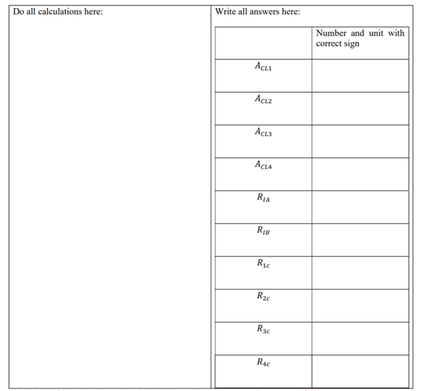
Transcribed Image Text:Write all answers here:
Do all calculations here:
Number and unit with
correct sign
AcLı
Acı2
ACL3
ACLA
R1A
R2c
R3c
R4c
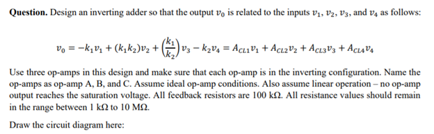
Transcribed Image Text:Question. Design an inverting adder so that the output vo is related to the inputs vị, vV2, V3, and v4 as follows:
vo = -k,v, + (k,k2)v2 +
V3 – kzv4 = AcLıVi + Acı2V2 + Acı3V3 + AcıaV4
Use three op-amps in this design and make sure that each op-amp is in the inverting configuration. Name the
op-amps as op-amp A, B, and C. Assume ideal op-amp conditions. Also assume linear operation – no op-amp
output reaches the saturation voltage. All feedback resistors are 100 k2. All resistance values should remain
in the range between 1 k2 to 10 M2.
Draw the circuit diagram here:
Expert Solution

Step by step
Solved in 9 steps with 2 images

Knowledge Booster


Learn more about
Need a deep-dive on the concept behind this application? Look no further. Learn more about this topic, electrical-engineering and related others by exploring similar questions and additional content below.Recommended textbooks for you
Delmar's Standard Textbook Of Electricity
Electrical Engineering
ISBN:
9781337900348
Author:
Stephen L. Herman
Publisher:
Cengage Learning
Delmar's Standard Textbook Of Electricity
Electrical Engineering
ISBN:
9781337900348
Author:
Stephen L. Herman
Publisher:
Cengage Learning