R = 100 R2 = 40N 2. For the circuit with the known values of its elements indicated in the figure and I3=0.2 A, a) find R3 and b) calculate I, and I2. & = 6V R3 Ez = 12V
Q: or the circuit show rove that E R3 R + R2 + R3 R1 V1 - CR2 V3 R3 Figure 2
A: Current flowing in the circuit I= E/(R1+R2+R3)
Q: Electrical circuits can usually be considered as an interconnection of lumped elements. FIGURE Q1…
A:
Q: For the circuit shown, identify two loops that are not meshes.
A: The mesh is a close path in a circuit which does not contain any close path in itself. The loop…
Q: Q3: For the following circuit, write Mesh equations for loops i1, i2 and i3 and then find the…
A:
Q: R1 R3 + V1 R2 R4 Vo I34 = 2kN. %3D Find I and V, in the circuit shown given that V1 = 12V, R1 = 5kN,…
A: Given circuit, Where, V1=12 VR1=5 kΩR2=19 kΩR3=20 kΩR4=2 kΩ
Q: (b) In the circuit shown in Figure Q3(b), (i) Find the value of open circuit voltage, VTH and…
A:
Q: 1. Electrical circuits can usually be considered as an interconnection of lumped elements. FIGURE Q1…
A:
Q: For the circuit shown „IC2 = 1mA ,VCE1 = 2V , and VCE2 = 5V 1. The value of RC is equal to 수 |ohm 2.…
A: We will use bjt current relationship and ohm 's law to find out unknown resistance
Q: Q2 Find out the value I1, I2, I3 I4 and Is in following circuit. | i5 | 14 22 40 V
A:
Q: For the circuit shown, identify two paths that are not loops or essential branches.
A: Loops in circuits: Loops are any closed circuit in circuits. So, here path becfg and baceg are not…
Q: Q5/ Determine the values of i3, v4, i5, andv6 in circuit shown in Figure + v1 12 2 18 Q a - V4 + 18…
A:
Q: (b) For the circuit shown in Figure Q1 (b), use mesh analysis to find it, iz, i3. 4 k2 4 k2 4 k2 ww…
A: To find mesh currents i1 , i2, and i3
Q: Solve the current flowing in R3 by Source transformation R, R3 10 B, 28 V E R2 7 V B2
A:
Q: HI PLEASE HELP ME SOLVE FOR V1,V2,V3, I1, I2, I3, TOTAL CURRENT VT = 50V R1=201 R2=420 R3=16…
A: Given that VT = 50V R1=201 R2=420 R3=16
Q: Consider the circuit shown below, where S is the source of alternating positive current, and Load…
A: Diode will conduct when anode potential is greater than cathode potential. VA-VK>0 During…
Q: (i) Use Thevenin's theorem to find the current flowing through RL N resistor shown in figure. R1=5…
A: The complete solution is as follows.
Q: In the circuit shown in Figure through the resistor R, is I4 = 0.4 mA. Find the voltage V, and…
A: ELECTRICAL NETWORK: When addressing a circuit problem or constructing a balanced circuit, the word…
Q: R1 R2 A R5 В R4 R3 R6 R7 The circuit above has R1 = 820 2, R2 = 220 2, R3 = 470 N, R4 = 910 Q, R5 =…
A:
Q: Q.1/ For the circuit shown below: Given Rt and Is a. Find the resistor R1 for the following circuit.…
A: Dear,as per company guidelines we can answer only one question at a time, kindly post other question…
Q: Use the voltage divider principle to find the value of v2 as shown in the figure below. Given: R₁ =…
A: Given circuit:
Q: write the final equation of point V2 * V4 () 3 A 4Ω 82 V2 V3 ww { 42 21, 2 A4) ww 2. ww
A:
Q: R1 R2 A R5 В R4 R3 R6 R7 The circuit above has R1 = 820 Q, R2 = 220 Q, R3 = 470 2, R4 = 910 Q, R5 =…
A:
Q: Which of these equations is correct (choose one only)? O V2= A*V2 - B*12 O V1= A*V1 - B*12 O V1=…
A:
Q: Determine the mathematical model equations for the electrical circuit shown in figure 2. The circuit…
A:
Q: نقطة واحدة Find V2 using the circuit of .Figure down R1 v2 i1 13 R3 Vs i2 R2 v3 R4 i1 11=12+13 O…
A: KCL stands for Kirchoff's current law which states that at any junction or any node total incoming…
Q: +3 V R2 -3 V
A: Given: w/ l is 3 volt Vt: 0.6 volt, Kn ; 200 ma/V"2 Vd : 1v ,Vs: -1 volt , Vg= 0v
Q: 2. Let R1, R2 and R3 be 1k, 4k and 12k respectively. What will the value of VRI and Ir3 in the…
A:
Q: For the circuit shown ,IC2 = 1mA,VCE1 = 2V, and VCE2 = 5V %D 1. The value of RC is equal to + ohm 2.…
A: So we need to find the various resistance values from the circuit.
Q: , = 8 A R, { 4 0 R2 20 N R,
A:
Q: Solve the value of vi, i1, v2 and iz in the circuit of Figure Q1(a). A = 10 Q1 (a) B= 21 12Ω + v,-…
A:
Q: a) By carefully observing the circuit, Find the between lok s,4KS2 and resistors loccated on side of…
A: According to company policy we are allowed to provide solution for only 3 sub parts of one question.…
Q: 1. Electrical circuits can usually be considered as an interconnection of lumped elements. FIGURE Q1…
A:
Q: 1-Write the mesh current equations for this circuit (You don't need to solve the equations to obtain…
A: PRESENCE OF SOURCE: In the presence of sources all the passive elements which are R, L and C always…
Q: P 4.3-14 The voltage source in the circuit shown in Figure P 4.3-14 supplies 83.802 W. The current…
A: Nodal voltages
Q: R1 R21 R4 Vo Vs R3 For the circuit given in the figure, Vs=12V, R1 = 12 Ohm, R2= 8 Ohm, R3=10 Ohm…
A:
Q: From the figure shown, the short-circuit current, Isc (Norton's equivalent Current) external to R2 i
A:
Q: (b) In the circuit shown in Figure Q3(b), (i) Find the value of open circuit voltage, VTH and…
A:
Q: Refer to the circuit of figure below, find ZT. R2 = 20 k2 1 µAZ0° R3 400 k2 Xc 50 k2 XL2 40 k2 I3
A: SERIES IMPEDANCE: Two or more elements are said to be in series if the current flowing them are…
Q: R2 R3 20 11 R4 20 R1 = 0 2A R6 30 V1 R5 120 12V V2 8V Solve the circuit to find: i. the current…
A: As per Bartleby guidelines, we are allowed to solve only three subparts, please ask the rest again.
Q: Q5/ Determine the values of i3, v4, i5, andv6 in circuit shown in Figure + v1 12 2 18 2 a b - U4 +…
A:
Q: of Ri to achieve this goal? b) Suppose you build the circuit using your calculated value for R1 from…
A: KIRCHHOFF’S LAW: KCL: The algebraic sum of all currents at a node is zero. Kirchhoff's current law…
Q: Q3// Find the current l2 through the 12-kohm, by using the SUPERPOSITION THE figure below. R1 12 k2…
A:
Q: By using the circuit shown below. R1 IT = 30 12 R2 = 42 12v R4 = 60 R3 = 20 %3D B Calculate: a- The…
A: PART (a) The total or equivalent resistance can be calculated as, Rtotal=R1+R2+R3||(R4)Rtotal=3 Ω+4…
Q: In the circuit given below, R = 45 Ω. Find the currents I1 through I4 and the voltage v0.…
A:
Q: Consider the circuit shown in the Figure below, the value of the current source I = 6A, voltage…
A: given data:
Q: (c) For the circuit shown in Figure Q2 (c).Determine i, to is. 122 ww is 600 V 16 2 |i4 82 |is 42…
A: Circuit simplified
Q: For the circuit shown ,IC2 = 1mA,VCE1 2V, and VCE2 = 5V 수 | ohm 1. The value of RC is equal to 수 |…
A: We will use the bjt current relationship. And ohm's law to find out unknown parameter.
Q: Q1) Using node voltage analysis in the circuit of Figure below, find the current i through the…
A: Nodal analysis uses Kirchhoff's current law and ohm's law. The detailed solution is provided below.
Q: E2. R3 R1 E1 Ali AR 16 6-
A: Simple problem on network analysis. Look below for solution. :-
please solve questions 2 and 3
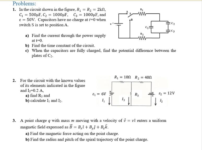
Step by step
Solved in 3 steps with 3 images
- Consider the circuit shown in the figure, with ε=36.0V,R0=50.0Ω,R=150Ω andL=4.00H. (a) Switch S1 is closed. Just after S1 is closed, what are the current i0 through R0 andthe potential differences VAC and VCB? (b) After S1 has been closed a long time so that the current has reached its final, steadyvalue, what are i0 , VAC and VCB? (c) Find the expressions for i0 , VAC and VCB as functions of time since S1 was closed.Do your results agree with what you get in (a) and (b) ? Graph i0 , VAC and VCB as afunction of time.Bioelectrical impedance analysis is a commercially available method used to estimate body fat percentage. The device applies a small potential between two parts of the patient's body and measures the current that flows through. With an estimate of the resistance individually of the muscle and fat between the two points, the composition of the tissue can be estimated. Assume that the muscle and fat tissue can be modeled as resistors in parallel. a) If a potential difference of 5 V is applied across the patient's arm, what is the potential drop across the patient's fat? b) If the measured resistance of the patient's arm is 750 Ω and the resistance of fat is 3 times that of muscle, what is the resistance of the muscle?The figure shows an electrical circuit with an ideal source ε1 = 12 [V], a real source ε2 = 9 [V] and r1 = 1 [Ω], eight resistors and two capacitors. Switches A and B areThey are originally open and the charge on the capacitors is zero. If switch A closes (B remains open), determine:a) The currents of the resistors R2 and R5.b) The potential difference between b and c, that is, Vbc. Indicate which point is at the greatest potential.c) The power supplied by the real source ε2.
- Vbatt=25 VC1=90 ?CC2=75 ?CC3=60 ?CR1=160 ΩR2=120 Ωt2=21.6 msect3=27 msecConsider the circuit shown below which shows a battery connected to some resistors and capacitors along with some switches which will be toggled opened or closed at different times. The components are listed above. The capacitances are in microFarads (?F), the resitances are in Ohms (Ω), and the times are in milliseconds (msec). A stopwatch is started at time t1=0 ms. At that time, switch S1 is closed and all other switches are open and the capacitor is allowed to charge up.(a). (i)What is the charge (in uC) on C1 at the time the stopwatch reads t2=21.6 ms?a)3690 b)1520 c)5710 d)2630 e)683 f)1750 (a).(ii)What is the current (in mA) through R1 at t2=21.6 ms?34.9 30.4 114 13.6 73.6 52.4 (b)(i)What is the voltage (in V) across R1 at t2=21.6 ms?8.37 5.58 2.18 11.8 18.2 4.85(ii). What is the voltage (in V) across C1 at t2=21.6 ms?63.2 29.1 40.9 7.57 19.4 16.9(c). (i) What is the energy (in mJ) in C1 at t2=21.6 ms?6.63…the emf source, E=3.2 V, of the circuit shown in the figure has negligible internal resistance. the resistors have resistances R1=3 ohm and R2=4.2 ohm. the capacitor has a capacitance C= 3.1uF. A) determine the time constant t , in units of microseconds for charging the capacitor. B) what is the charge Q on the capacitor in units of microcoulomb?A potential difference V(t) = V0sin ωt ismaintained across a parallel-plate capacitor withcapacitance C consisting of two circular parallel plates. Athin wire with resistance R connects the centers of the twoplates, allowing charge to leak between plates while theyare charging.(a) Obtain expressions for the leakage current Ires(t) in thethin wire. Use these results to obtain an expression for thecurrent Ireal(t) in the wires connected to the capacitor.(b) Find the displacement current in the space between theplates from the changing electric field between the plates.(c) Compare Ireal(t) with the sum of the displacementChapter 16 | Electromagnetic Waves 733current Id(t) and resistor current Ires(t) between theplates, and explain why the relationship you observe wouldbe expected.
- As shown, the battery has emf ε = 18.0 V and the other circuit elements have values L = 0.400 H, R1 = 2.00 kΩ, and R2 = 6.00 kΩ. The switch is closed for t < 0, and steady-state conditions are established. The switch is then opened at t = 0. (a) Find the emf across L immediately after t = 0. (b) Which end of the coil, a or b, is at the higher potential? (c) Make graphs of the currents in R1 and in R2 as a function of time, treating the steady-state directions as positive. Show values before and after t = 0. (d) At what moment after t = 0 does the current in R2 have the value 2.00 mA?A series resistance of 10 ohms and a capacitance of 0.1 F are connected to a 100-V source. The charge is zero at t = 0. (a) Obtain the equation of the charge at any time t. (b) At what time the current be 5 amp?The circuit shown in Figure-2 is at steady state before the switch closes at time t = 0. The input to the circuit is the voltage of the voltage source, 12 V. The output of this circuit is the voltage across the capacitor, v(t). -Use Matlab Simscape Electrical to build and plot the output, v(t), as a function of t (by using scope). Use the plot to obtain an analytic representation of v(t) for t > 0. Hint: We expect v(t) = A + Be–t/τ for t > 0, where A, B, and τ are constants to be determined. Modify the circuit given in this example (build figure-2) https://www.mathworks.com/help/physmod/simscape/ug/operating-point-rlc-transient-response.html You will obtain a graph as figure 2-b and by using graph and substituting three ‘t’ values to v(t) then you can find A, B and τ.
- What is a Linear Circuit? Simply we can say that the linear circuit is an electric circuit (Links to an external site.) and the parameters of this circuit are resistance, capacitance, inductance and etc are constant. Or we can say the parameters of the circuits are not changed with respect to the voltage and current is called the linear circuit. What is a Non-Linear Circuit? The non-linear circuit is also an electric circuit and the parameters of this circuit differ with respect to the current and the voltage. Or in the electric circuit, the parameters like waveforms, resistance, inductance and etc are not constant is called as Non- linear circuit. Question: Is it possible to apply superposition theorem to nonlinear circuit? If yes, why? and if no, why?The figure shows an electrical circuit with an ideal source ε1 = 12 [V], a real source ε2 = 9 [V] and r1 = 1 [Ω], eight resistors and two capacitors. Switches A and B areThey are originally open and the charge on the capacitors is zero. If at t = 0 [s] switch A opens and switch B closes, determine:d) The potential difference of resistor R8 at t = 2.6 [s].e) The time required for the potential difference of the equivalent capacitor to reach the maximum possible value. Justify your answer.A battery of emf 30.0 V is connected to a switch, an inductor of inductance ? = 0.600 ? and two resistors, R1 = 10.0 ? and R2 = 6.00?. The switch is initially open. A. What are the values of currents ?1, ?2, ?3 just after the switch is closed? (Just give an answer) ?1 = ?2 = ?3 = B.)Which point, a or b, is at higher potential or are they at the same potential, just after switch S is closed? (Just give an answer) C. What is the value of current ?1 through the battery a long time after the switch is closed? Show your work and briefly explain your logic