R1 R21 R4 Vo Vs R3 
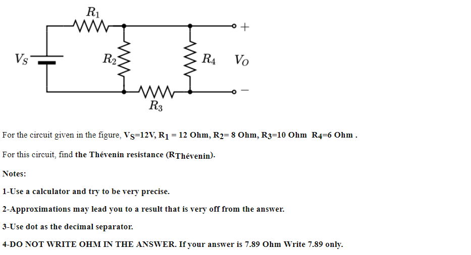
For the circuit given in the figure, Vs=12V, R1 = 12 Ohm, R2= 8 Ohm, R3=10 Ohm R4=6 Ohm . For this circuit, find the Thévenin resistance (RThévenin).
Q: 30오 952 B 252 A RI R3 R5 R, 을6OR2 Ra 402 Re 5요 Ry 4 402 R6z15e 32 25오 10요 R8 Ry LA1
A:
Q: Find the values for R1, R2 and R3 in the below circuit to design a circuit with a gain of 36. The…
A:
Q: 13 Ω a 25 N R1$50 N R2 50 Ω R3 R5 R4$20 N 30 N b
A: Given circuit shown
Q: Q3/ In the following figure, the first resistance (R1 = 252) and the second resistance (R2= 1252),…
A: We need to find out value of resistance of given circuit
Q: Riz Rz Us
A:
Q: Using node voltage analysis in the circuit of FigureP3.9, find the current i through the voltage…
A: The circuit diagram is,
Q: Use mesh-current analysis to find the value of v in the circuit of Figure P2.38.
A: Given data, The value of resistance R1 = 20 Ω The value of resistance R2 = 20 Ω The value of…
Q: V₁ = √₂=0v -5 V 144 Si 此 Si -V₂ 2.2 ΚΩ 8-5 V
A:
Q: For the Circuit show below, D1, D2 and D3 are identical having VD-0.7V. Find the currents I1, I2,…
A:
Q: Q2/ Use Thevenin's theorem, to find the value of load resistance RL in the circuit of Figure below…
A:
Q: 5. Find the equivalent resistance Rab (in ohms) of the circuit shown by using a Wye-to-Delta…
A: Find the equivalent resistance between the two points a and b ?
Q: Given the circuit below where Vs=5 V, R1=2 Q, R2 = 2 Q, and R3 =2 Q, you are going to solve for 1,…
A:
Q: Using node voltage analysis, find the voltages V1 and V2 for the circuit of Figure P3.2.
A: Apply nodal analysis at
Q: R1 VR, Vr, R2 For the circuit shown above use Kircho's laws to compute the voltage VR, across…
A:
Q: Use mesh analysis to solve for V in the circuit below. Vs = 20 V, R₁ = 30 02, R2 = 50 Q, R3 = 20 Q,…
A: Given that: VS=20 V, R1=30 Ω, R2=50 Ω, R3=20 ΩR4=30 Ω, R5=40 Ω, R6=60 Ω, R7=80 Ω A circuit is shown…
Q: Determine r2 using product/sum rule. RT=40 ohms R1=200 ohms R2=? Solve using this equation "RT=(R1 X…
A:
Q: R2 Q.43: For the circuit shown in figure beside, select the values of R1, R2 & R3 so that: 1=0.5v,…
A:
Q: Q1) for the circuit shown find voltage at R1 and the current D1 ideal Kt +5V R1 1k R2 1k GND
A: The given circuit is,
Q: 1. Testing the Maximum Power transfer to a load with Thevenin Resistance. For the circuit given…
A:
Q: 5. For the given circuit below, provide the following unknowns: RS RI = 1.2k2 R2 = 2.2k2 R3 R3 =…
A:
Q: 2) a. For the circuit shown below, use the Branch Current Method to find an expression for i3 in…
A:
Q: Q3/ In the following figure, the first resistance (R, =250) and the second resistance (R2= 1252),…
A:
Q: Q4/ In the following figure, the first resistance (R1 = 202) and the second resistance (R2 = 1002),…
A: The solution can be achieved as follows.
Q: В |C D The branch currents h, 2, 3, and l4 are А, A, A, and |A, respectively.
A: The given circuit with proper markings can be drawn as: According to KCL Sum of incoming…
Q: Ехample: Using loop equations to find the current I, in the circuit in Figure below. R2 R4 102 R3…
A: The given circuit is:
Q: The analysis of the voltage, V for the circuit given in Figure Q4 can be expressed in the following…
A: Id =0.2247 V3 =200 Id =200×0.2247 =44.94 V
Q: Using KCL, perform node analysis on the circuitshown in Figure P3.24, and determine the…
A: First, draw the circuit by assigning the values of the parameters as mentioned in the question. The…
Q: Example: find VR3 for the circuit shown in Figure below. If VRI= 18 V and VR2 = 12 V. R1 bas + VR1 5…
A:
Q: R1 R2 I, .42: For the circuit shown in figure beside, select the values of R,, R2 & R3 so that:…
A:
Q: (a) Given that RI= 10 Q, R2= 25 Q, R3= 60 Q, R4= 20 Q, R5= 24 N, R6= 20 Q, R7= 50 Q and R8= 30 Q,…
A: For the given circuit we have to find the value of current I and voltage Vo
Q: Given R1=15 Ω,R2=5 Ω,R3=20 Ω,R4=10 Ω,R5=8 Ω,R6=4 Ω,and Is=5 A, solve for the node voltages shown in…
A: We have to find the node voltages from the above figure; R1= 15 Ω,R2=5Ω,R3=20Ω,R4=10Ω,R5=4Ω,IS=5 A
Q: +3 V R2 -3 V
A: Given: w/ l is 3 volt Vt: 0.6 volt, Kn ; 200 ma/V"2 Vd : 1v ,Vs: -1 volt , Vg= 0v
Q: In the circuit given in the figure, the values shown by the ampermeters A, and A2 are l, and 12…
A: Fig: Given circuit Assume that voltage drop across ammeter is zero
Q: P1: Determine the total resistance in the circuit below when all independent current sources are…
A:
Q: Consider the current steering circuit. The values of Iref, I2 and I6 are mentioned on the circuit .…
A:
Q: 4. Find the Norton equivalent circuit seen by RLoad. For this part, DO NOT physically apply a short…
A: For the following circuit we have to answer the questions given here
Q: Given R1=4 Ω,R2=5 Ω,R3=8 Ω,R4=10 Ω,R5=2 Ω, and Is=2 A, solve for the node voltages shown in Figure…
A: write KCL equations, v2-v15+v2-v38-2=013v2-8v1-5v3=80…
Q: Q4/ For the circuit in figure below, find i and in2 for the cases of supply voltage (VS) 20 V, 12 V,…
A: Given: VZ1=13VVZ2=7VAssume diode D3 is idealCondition for conduction od Zener diode is:VA>VZ1 ,…
Q: If we measure the voltage at the terminals of a two-terminal network with two known (anddifferent)…
A: From the above circuit when 1000 ohm is connected, the voltage across it is 8 V:…
Q: 4. Use The venin's theorem to find the current flowing in the resistor R5 for the circuit shown in…
A: Given circuit, R1=5R2=8R3=2R4=7R5=3R6=4EV1=16 V2=14
Q: R1 For the circuit shown in figure beside, select the values of R1, R2 & R3 so that: y1=0.5v,…
A:
Q: HW2.1- Find the values in the circuit if the current through the 36Q resistor is Is = 5,4 A.…
A:
Q: (b) In the circuit shown in Figure Q3(b), (i) Find the value of open circuit voltage, VTH and…
A:
Q: Refer to the circuit of figure below, find ZT. R2 = 20 k2 1 µAZ0° R3 400 k2 Xc 50 k2 XL2 40 k2 I3
A: SERIES IMPEDANCE: Two or more elements are said to be in series if the current flowing them are…
Q: Refer to the given circuit below. Using Superposition Theorem, determine the percent contribution of…
A:
Q: Given the circuit in figure, calculate the expression of Vu and its value when a=100, gm=200mS,…
A: Current through R2, iR2=(gm)(Vx)-10........(applying KCL(Kirchhoff's Current Law) at the top node of…
Q: Vị 4 V R3 1N R5 R2 R6 (1) Is, 2 A R1 R4 Is2 4 A www.solved-problems.com
A: Here,
Q: 6- find the suitable total voltage (VT) for the circuit diagram shown in Figure (f) R1=30 IT-10A…
A: When equal resistances are connected in parallel then-current divides equally. this can be analyzed…
Q: The Wheatstone bridge in the circuit is balanced when R3 equals 3000 ohm. If the galvanometer has a…
A:
Q: 3. Complete the table given the series-parallel circuit below. 40 100 R4 R1 ww ww SV + R1 R2 R3 R4…
A:
Trending now
This is a popular solution!
Step by step
Solved in 2 steps with 2 images
- for this the solution just said non-inverting v0=vs((10k/10k )+1) v0=2vs first of all what is non-inverting and how do i know if it is inverting or non-inverting and what is the difference between both in application? and how did he just get the other equation? i dont get it. please explain everything in a lot of detail and provide an altered question for one that is inverted and solve it so i can understand the difference in application. thank you!For the circuit in the figure, draw the equivalent circuit and values I1, I2 and ID1, ID2.find? need handwritten only ,otherwise downvote.)a) Given that the circuit in the figure makes io= A(v2-v1)-(1/Ro)VL, find expressions for A and Ro, as well as the condition between the resistors so that Ro=∞. b) Discuss the effect of using 1% resistors.
- Please explain step by step that how to solve the equations to get the values of v1 and v2? ..Nodal analysis is another very useful way to obtain information regarding a circuit.electric. For example, consider the 4 Ω resistor in the circuit shown below. Nodal tension to your left was named V1, while the right was named V2. Therefore, determine the values of these tensions. answer:v1 = 9,43 V ; v2 = 11,15 VAny linear circuit can be simplified. This is what the Thevenin Theorem states. Per complex as it is, it can be reduced to a single source of voltage and a resistance. These are normally connected in series to a load resistor, which is usually variable. When analyzing a figure presented below, check whether a load that has been connected to the circuit to the left of terminals A and B. Therefore, determine a voltage and imposed resistance on it, that is, the Thevenin voltage and resistance, representative of this circuit
- Please help me solve for the total resistance, total current, and individual voltage if: VT = 30 VR1 = 7 ohmsR2 = 10 ohmsR3 = 6 ohmsR4 = 4 ohmsR5 = 8 ohmsR6 = 9 ohmsR7 = 5 ohmsR8 = 12 ohmsR9 = 3 ohmsR10 = 8 ohmsSometimes, we can use symmetry considerations to find the resistance of a circuit thatcannot be reduced by series or parallel combinations. A classic problem of this type is illustratedin Figure P2.16. Twelve 1-Ω resistors are arranged on the edges of a cube, and terminals a andb are connected to diagonally opposite corners of the cube. The problem is to find the resistancebetween the terminals. Approach the problem this way: Assume that 1 A of current enters terminal a and exits through terminal b. Then, the voltage between terminals a and b is equal tothe unknown resistance. By symmetry considerations, we can find the current in each resistor.Then, using KVL, we can find the voltage between a and b.As with the nodal analysis, the analysis of meshes for an electrical circuit is quite advantageous. This is because it also, to be developed, does not need a high number of equations. In practice, the main objective of this technique is to search for the intensities of called mesh currents. This is what can be done in the circuit presented below. Case the analysis of its meshes is carried out on it, what will be the current intensities found?
- The terminal voltage and terminal current were measured on thedevice shown in P2.14(a). The values of v and i are given in thetable of P2.14(b). Use the values in the table to construct a circuitmodel for the device consisting of a single resistor from Appendix H.Virtual Lab: circuits and Kirchoff’s rules Go to: https://phet.colorado.edu/it/simulation/circuit-construction-kit-dc-virtual-labBuild each of the circuits in the figures, with the designed characteristics.For each of the circuits, show the calculations to find the current and the potential difference in eachelement of the circuit.In building the circuit in Figure 1) through the simulator, adjust the small resistance of the battery tozero and put in series a small resistance as required from the design.For instance, for E1 you will need abattery with V = 6V and you will need to put in series a small resistance of 0.5 Ω to simulate the smallresistance in a battery.Figure 1)Figure 2)This is a practice problem from the Signals and Systems course in my Electrical Engineering program. Could you please walk me through the steps of solving it so that I can solve more complicated ones in the future? Thank you for your assistance.