R1 = 10kΩ Rf = 2kΩ. Record the amplitude of the signal source (vg), the ac component of the output (vout), and the dc component of the output (VOUT) in Table 3. Test to see whether you have met your design criteria. The measurements that you made in Tab
R1 = 10kΩ Rf = 2kΩ. Record the amplitude of the signal source (vg), the ac component of the output (vout), and the dc component of the output (VOUT) in Table 3. Test to see whether you have met your design criteria. The measurements that you made in Tab

Chapter28: Overcurrent Protection–fuses And Circuit Breakers
Section: Chapter Questions
Problem 11R: State four possible combinations of service equipment that meet the requirements of 110.9 and 110.10...

Related questions

Question
The partial gain for Vg is -2 ±10%
R2 = 1kΩ.
R1 = 10kΩ
Rf = 2kΩ.
Record the amplitude of the signal source (vg), the ac component of the output (vout), and the dc component of the output (VOUT) in Table 3. Test to see whether you have met your design criteria. The measurements that you made in Table 3 should assist you in this. Show the results of your comparisons in Table 4.
![+15[V]
1
10[k]
-15[M]
R1
WT
R2
P4
www
VOUT](/v2/_next/image?url=https%3A%2F%2Fcontent.bartleby.com%2Fqna-images%2Fquestion%2F5ecf1484-f95f-4119-9858-43c8382b92c0%2Fc4ea6a90-7bbd-4fc8-b9b2-c017811ae31e%2Ftgxb0wi_processed.jpeg&w=3840&q=75)
Transcribed Image Text:+15[V]
1
10[k]
-15[M]
R1
WT
R2
P4
www
VOUT
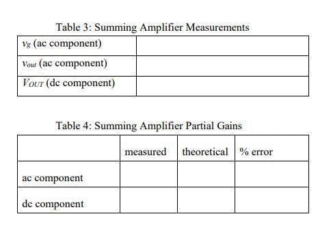
Transcribed Image Text:Table 3: Summing Amplifier Measurements
Vg (ac component)
Vour (ac component)
Vour (de component)
Table 4: Summing Amplifier Partial Gains
ac component
de component
measured theoretical % error
Expert Solution
This question has been solved!
Explore an expertly crafted, step-by-step solution for a thorough understanding of key concepts.

Step by step
Solved in 3 steps

Knowledge Booster


Learn more about
Need a deep-dive on the concept behind this application? Look no further. Learn more about this topic, electrical-engineering and related others by exploring similar questions and additional content below.Recommended textbooks for you
EBK ELECTRICAL WIRING RESIDENTIAL
Electrical Engineering
ISBN:
9781337516549
Author:
Simmons
Publisher:
CENGAGE LEARNING - CONSIGNMENT
EBK ELECTRICAL WIRING RESIDENTIAL
Electrical Engineering
ISBN:
9781337516549
Author:
Simmons
Publisher:
CENGAGE LEARNING - CONSIGNMENT