Circuit Diagram V1 C1 220 Vrms 10uF 60 Hz 0° Computed Values Compute the expected power factor of the circuit given the different capacitance. L (RMS) Capacitance (uF) Real Power (Watts) Reactive Power (Vars) Power Factor mag (A) 100 90 8888 70 60 50 40 30 20 10 0 R1 L1 50Q 10mH
Circuit Diagram V1 C1 220 Vrms 10uF 60 Hz 0° Computed Values Compute the expected power factor of the circuit given the different capacitance. L (RMS) Capacitance (uF) Real Power (Watts) Reactive Power (Vars) Power Factor mag (A) 100 90 8888 70 60 50 40 30 20 10 0 R1 L1 50Q 10mH

Power System Analysis and Design (MindTap Course List)
6th Edition
ISBN:9781305632134
Author:J. Duncan Glover, Thomas Overbye, Mulukutla S. Sarma
Publisher:J. Duncan Glover, Thomas Overbye, Mulukutla S. Sarma
Chapter2: Fundamentals
Section: Chapter Questions
Problem 2.27P: An industrial load consisting of a bank of induction motors consumes 50 kW at a power factor of 0.8...

Related questions

Question
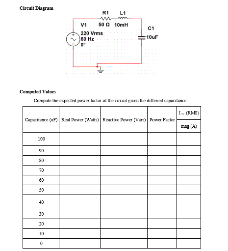
Transcribed Image Text:Circuit Diagram
V1
C1
220 Vrms
10uF
60 Hz
0⁰
Computed Values
Compute the expected power factor of the circuit given the different capacitance.
I (RMS)
Capacitance (uF) Real Power (Watts) Reactive Power (Vars) Power Factor
mag (A)
100
90
80
70
60
50
40
30
20
10
0
R1
L1
mm
50Q 10mH
HE
Expert Solution
This question has been solved!
Explore an expertly crafted, step-by-step solution for a thorough understanding of key concepts.

Step by step
Solved in 8 steps with 1 images

Follow-up Questions
Read through expert solutions to related follow-up questions below.
Follow-up Question

Transcribed Image Text:Circuit Diagram
V1
R1
220 Vrms
• 50 Ω
60 Hz
0.⁰
L1
100mH
Computed Values
Compute the expected power factor of the circuit given the different capacitance.
Reactive
ITotal (RMS)
Capacitance Real Power
Power
Power
(UF)
(Watts)
Factor
(Vars)
mag (A)
100
90
80
70
60
50
40
30
20
10
C1
100uF
Solution
Follow-up Question
Compute the expected power factor of the circuit given the different capacitance.

Transcribed Image Text:R1
L1
50 2 10mH
V1
C1
220 Vrms
10uF
60 Hz
0°
Computed Values
Compute the expected power factor of the circuit given the different capacitance.
IT (RMS)
Capacitance (UF) Real Power (Watts) Reactive Power (Vars) Power Factor
mag (A)
10
Solution
Follow-up Question
Compute the expected power factor of the circuit given the different capacitance.

Transcribed Image Text:R1
L1
www
50Q 10mH
V1
C1
220 Vrms
10uF
60 Hz
0°
Computed Values
Compute the expected power factor of the circuit given the different capacitance.
IToal_(RMS)
Capacitance (UF) Real Power (Watts) Reactive Power (Vars) Power Factor
mag (A)
70
60
50|
Solution
Knowledge Booster


Learn more about
Need a deep-dive on the concept behind this application? Look no further. Learn more about this topic, electrical-engineering and related others by exploring similar questions and additional content below.Recommended textbooks for you
Power System Analysis and Design (MindTap Course …
Electrical Engineering
ISBN:
9781305632134
Author:
J. Duncan Glover, Thomas Overbye, Mulukutla S. Sarma
Publisher:
Cengage Learning
Power System Analysis and Design (MindTap Course …
Electrical Engineering
ISBN:
9781305632134
Author:
J. Duncan Glover, Thomas Overbye, Mulukutla S. Sarma
Publisher:
Cengage Learning