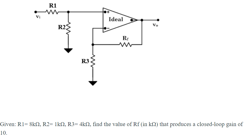
R1 Vi Ideal R2 Vo Rr R3


Q: VAB S SRo R1 220 2 R2 Vs 50 V R3 470 (2 RL 220 0 Vas 470 2 R4 330
A: For this problem we can easily find Vab by applying nodal analysis.
Q: Vdd Vdd Vdd R2 R4 R6 Vo1 Vin2 Vo R5
A:
Q: V1 120 V R1 20 R2 R3 + v2 110 V R4 32 0 R5 10Ω R6 20
A: KIRCHOFF'S CURRENT LAW:- The algebraic sum of every current entering and leaving the node has to be…
Q: 4Ω R1 I2 R2 lenil+ Ile 10 V R3320 2 E = 12 V E2- Solution
A:
Q: What is the value of 1, 12,13 ,14, Vr1, Vr2 Vr3,Vr4 if R1= 10 , R2=7, R3=5, R4=8 R2 AAA I2 R1 20V R3…
A: Redraw the circuit and represent the node voltages.
Q: Find the value of voltages, v1, V2, V3, V4 and v5 in the circuit given below. 67 µF 92 µF valla V1…
A: Calculate the equivalent capacitance of C1 and C2. CA=C1+C2=67 μF+112 μF=179 μF
Q: 16 V 3.9 kn Ice o Vc 62 kn VB VCEQ B = 80 IBQ VE 9.1 k2 0.68 k2
A: A transistor is a semiconductor device that is constructed by sandwiching three n-p-n or p-n-p…
Q: +V +1 C3 911 7 R5 8 R6 1.80 1.80 V2 2.23Vpk 50HZ -26.35° 1.33mF L3 7.3mH
A:
Q: Given R1 R2 R3 R4 R5 Е1 E2 120 10 130 17 24 50 100 Rz I, Iz It In
A: First we will do source transformation then by using of krichoff's current law we will find out…
Q: Q1. R1 = 100 k2, R2 = 3 kN, R3 = 12 kN, C1 = 0.47 uF and v;(t) = 2cos(100t+45°). Determine %3D %3|…
A:
Q: 13 I R3 Vx R1 R2 R4 v2 O V1
A:
Q: R3 R4 Vo Il i,1R2 R1 R5 power dissipated R1= power dissipated R2= +
A: Since you have asked multiple questions in a single request, we will be answering only the first…
Q: Itotal R1 13 1002 R2 E R3 2202 6V 3302 Fig. 1: Circuit Digram
A: Here we should construct the circuit in the simulator and do the theoretical calculations to verify…
Q: R6 R2 R1 Vdc R3 R5 R4
A: First we will find voltages and current in each branch , and then will verify the KCL and KVL. Let…
Q: Nodal Analysis Calculation steps: Note: VB = 2.688 V Components Used: Part Values R1 1500 R2 200 Q…
A:
Q: Problem 1: Solve for the values of the currents IB, I1, I2, and 13 from the given circuit using M…
A:
Q: I. FIND THE UNKNOWN PARAMETERS. a. IRI b. IR2 IR3 R1 R3 R5 с. d. V R4 V R5 f. V е. V1 R2 R4 V2 R2…
A:
Q: 100V 비 2.=52 Ry=152 ~ 3 R2=52 R3=1022 m Ro=202 Find the TOTAL POWER of P1, P2,P3,P4, Psand Po ks:…
A:
Q: CONSIDERING R1=4800HMS, R2= 670 OHMS OMEGA AND E=11.5 V DETERMINE: A) THE THEVENIN TENSION [VTH] B)…
A:
Q: 8. a) RT: 9. a) RT: 12V +12V I R1=50 R3=60 A www R2=20 b) IT: ww REV (R2=120 b) Ammeter reads: R1=40…
A: 8- given:- R1=5 ohm, R2=12 ohm, R3= 6 ohm Voltage = 12V As we seen circuit Diagram All the registers…
Q: Determine the equivalent resistance between terminals a and b. O 13.0741 0 O 13.9765 0 EE O 14.9765…
A:
Q: I = 10 A 10 V 8 V 4 A P2 14 A P4 Ps 30 V P1 20 V P3 12 V 0.41
A: Calculating power p4 p4=VIp4=8×4p4=32 W Calculating power p5 p5=V2Rp5=1220.4p5=1440.4p5=360 W
Q: R, ac 82 20 2 I, 0.5 2 R2 6Ω E3 12 V E, - 18 V E2 3.0 V 0.5 Q 0.25 Q 12 E4 R4 e 0.75 Q 15 2 24 V
A: By mesh analysis we will find out current through circuit.
Q: R1 + Et = R2 R3 VR3
A: first find value of current in R2 and R3 then apply KVL in loop 1 we will get value of Et
Q: E₂ 18 V 1. For the above circuit: R₁ 6 Ω HI R₂ 3Ω R₂ 6 Ω
A:
Q: VI and V₂ : V₁ = 53. 914 L25.5° V₂ = 53. 988 4²9.7" SOLVE FOR Answer should be :
A: The given node equation can be solved by using the cramer's rule. It depends on the determinant of…
Q: mein ZE Voc* 10 v 19 kli VI hps 1ype 9118.2 0.22 t A to point A Y1. C2 1 HF Y2 Vou: G. Vin RL 1 kHz…
A: As per bartleby expert policy, only one individual question is to be answered. Kindly repost…
Q: R1 R2 2k2: 4kQ: R3 LA 80V V2 4000: ㄷ-40V ind: I1 =2 a. 22 mA b. 23 mA c. 24 mA d. 25 mA
A:
Q: Q4:- Determine the total resistancecRe) and the voltagel V) from the circuit of Fig - (4) loe + VI…
A: A simple question based on network analysis. In this we have to find the equivalent resistance and…
Q: I1 R1 R4 R6 Va Vb 3 5 4 12 V1 V2 13 R2 R3 12 6 12 20 3 R5 Vaend 10 Vaend Va
A:
Q: R2 V2 V1 31z R1 Va Iz R4 V4 R3 V3 3v 2Va 2Ω 10A Find R4
A:
Q: R1 R2 R3 A 20 Ix J13 R4 vi$200 It R5 12 $10 20 V v2 V= SL
A:
Q: Va R2 Vb 20 R1 40 12 11 3A R3 4A 30 1.33 V Find 4 V Va -1.33 V -4 V
A: Applying nodal analysis at node Va Va4+3 A+Va-Vb2=03Va4=Vb2-3 A........1 Applying nodal analysis at…
Q: Va R2 Vb 20 R1 40 12 11 ЗА R3 4A 30 1.33 V Find 4 V Va -1.33 V
A: According to the guidelines, the first question will be answered. From figure (a) Apply KCL at node…
Q: Determine IZ for the network shown with RL=220 ohms Rs + 3302 IR Vz = 10 V RL VL %3D 20 V = 400 mW…
A: From the Zener Regulator circuit
Q: 1k 14 1k R11, V2 R13 R9 1k 1k R10 R8 1k R12 S1k 11 12 13
A: Solve the above questions
Q: R3 30 R1 R2 20 V2 - Is + Vs R4 12 V +
A: we need to find IS and V2
Q: Find current through R2 resistor. R1 R3 Il 12 V1 10 Select one: О а. 2.43 ОБ. 3.75 c. 3.04 O d. 2.67…
A: Note:- Taking unit of resistance as ohm and unit of voltage supply as Volts and solving the…
Q: BT1 15+ R8 15k www R1 10k www · R2 30k + V1 www BT2 10 R5 15k W R3 30k V6 www + V3 R6 20k R7 20k 11…
A:
Q: R2 R3 U2 IDEAL IDEAL R1 Vsenwt R4 V[(R2+R3) / R2R4]
A: In this question we will find output current in opamp...
Q: 18 V Ip 2 kQ O Vp = 12 V VG 12 V o W VDs Ipss = 8 mA 680 k2 + VGS Vs 110 k2 0.68 kN FIG. 7.86…
A:
Q: Q.2 Determine Rrand / for the following network of Fig.2. ch P- 30v- B3 102 10 4 612 Fig.2 R1
A:
Q: Exercise 1 Calculate PN (power on nonlinear resistor) R1 R2 RN Given: E = 17,5 V, R1=2 Q, R2= R3 = 4…
A:
Q: Example 8.32: Compute 8-point DFT of the following sequence using DIF algorithm x(n) = 1 for0 <n<7…
A:
Q: Q1. Find VGSQ +18 V Ioss =10 mA Vp = -2 V 88 MQ V, a Rd = 40 kQ o V. 8 MQ 1.1 k2 Your answer
A:
Q: 2. V1 =20V V2 = 30V l = 2A 12= 1A R1= 100 R2= 20 FIND THE CURRENT FLOWING ALONG Rị USING…
A: To solve above problem, one should know about superposition theorem. It states that in any linear…
Q: VCC R1 R2 Vc Q1 R3
A:
Q: R1 = 10k %3D R1 R3 R2 = 14k %3D R3 = 12k R2 R4 R4 = 19R %3D What is the R total ?
A: Given circuit: R1=10 kΩR2=14 kΩR3=12 kΩR4=19 kΩ
Q: R2 R1 AC V-150*sin(314*t + 75) V, R1=100 Ohms, R2-50 Ohms, L=0.5 H. Current IL is: Выберите один…
A: Given circuit V=150sin(314t+75) vR1=100 ΩR2=50 ΩL=0.5 H
Q: Is 11 12 13 Vs R1 R2 R3 Select one: O a. I, * R1/(R+ R2+ R3) O b. I, * (R2 * R3))/(R1 * R2 + R2 *…
A: Using current division rule find the current I1

Step by step
Solved in 4 steps with 1 images


- Find an expression for the closed-loop gain G = v0/vS. Then, assume that R1 = 1kΩ, R2 = 4kΩ, C = 1uF.The amplifier as shown has R2 = 68 kΩ and R1 = 2.7 kΩ. What are the valuesof Av A, Av B, Av C, RinA, RinB, RinC, and RoutA, RoutB, RoutC, for the amplifier equivalent circuit as shown.The open-loop gain A of real (nonideal) op-amps isvery large at low frequencies but decreases markedlyas frequency increases. As a result, the closed-loopgain of op-amp circuits can be strongly dependent on frequency. Determine the relationship between a finiteand frequency-dependent open-loop gain AV(OL)(ω)and the closed-loop gain AV(CL)(ω) of an invertingamplifier as a function of frequency. Plot AV(CL)versus ω. Notice that −RF/RS is the low-frequencyclosed-loop gain.
- State and derived an expression for the closed loop gain of the circuit shown in fig. (2) i need the answer in 30 minutes pleaseDesign an inverting amplifier to provide a closed-loop voltage gain of Ay = -22 V/V. The maximum input voltage signal is 30 mV with a source resistance in the range of 1 kls R, < 3 kN. The variable source resistance should introduce a difference in the gain no more than a 2% of the gain factor. What is the range in output voltage?What would be the Q-point currents in M4 and M5 in the amplifier as shown if VDD = VSS = 16 V, I2 = 250 μA, RG = 7 kΩ, RL = 2 kΩ, and VT N = 0.75 V, VT P = −0.75 V, Kn = 5 mA/V2, and Kp = 2 mA/V2?
- (a) A non-inverting amplifier is implemented with two 10 kΩ resistors with 5% toleranceWhat is the range of possible values for gain A? (b) Repeat for an inverting amplifier.Present theoretical calculations and confirm results in simulator (multisim, proteus).Consider the active circuit:a. Assuming it's an ideal op amp, derive the circuit’s transfer function as a function of frequency, H(jw) in canonical form.b. We want a DC gain of 40dB. If the op amp has value of Rin = 10MΩ and Rout = 50Ω, choose appropriate values for R1 and R2. Explain why your selected values of R1 and R2 allow you to ignore Rin and Rout for the remainder of the problem.With the given circuit, you are tasked to do the ff: a. Write the node-voltage equations (where there must be one for eac input terminal of the op amp) b. The load current can be expressed as iL = AVin + BVL b.1 What is the expression for A? b.2 What should be the condition of resistors R1, R2, R3, & R4, so that B is zero? (which means this condition will allow iL depend only on Vin and not on RL)
- Q2. For the op-amp circuit as shown below, given that RS = 50.5 kΩ, RL = 9 kΩ, R1 = 10 kΩ, R2 = 11 kΩ, R3 = 6 kΩ, R4 = 4 kΩ, R5 = 1.8 kΩ. (a) Determine the voltage gain G1=vO1/vS: (b) Determine the voltage gain G2=vO/vS:What are the gain Av, input resistance, and output resistance of the three stage amplifier as shown (a) if R2 = 68 kΩ and R1 = 2.7 kΩ?Consider the active circuit with the schematic:a. Assuming it's an ideal op amp, derive the circuit’s transfer function as a function of frequency, H(jw). Make sure it in canonical form.b. We want a DC gain of 40dB. If the op amp has value of Rin = 10MΩ and Rout = 50Ω, choose appropriate values for R1 and R2. Explain why your selected values of R1 and R2 allow you to ignore Rin and Rout for the remainder of the problem. c. If L = 1H, sketch the straight-line approximation of the Bode plot for the circuit’s gain assuming the op amp can still be considered as ideal.d. The op amp you select turns out to be non-ideal, and it has a real pole at wC = 1krad/s. Write the updated transfer function for your circuit (using your values of R1, R2, and L = 1H). Make it in the canonical form.e. Sketch the straight-line approximation of the Bode plot for the circuit with your updated transfer function from D.