R2 1 R1 sC ●+ Vị V. Figure 15.4 Full Alternative Text +,

Power System Analysis and Design (MindTap Course List)
6th Edition
ISBN:9781305632134
Author:J. Duncan Glover, Thomas Overbye, Mulukutla S. Sarma
Publisher:J. Duncan Glover, Thomas Overbye, Mulukutla S. Sarma
Chapter13: Transmission Lines: Transient Operation
Section: Chapter Questions
Problem 13.19P

Related questions

Question
DESIGNPROBLEM_
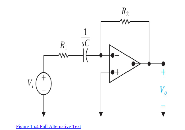
1. Use the circuit to design a high-pass filter with a cutoff
frequency of 2.5 kHz and a passband gain of 10 dB. Use a 50 nF
capacitor in the design.
2. Draw the circuit diagram of the filter and label all the components.
Transcribed Image Text:R2
1
R1
sC
●+
Vị
V.
Figure 15.4 Full Alternative Text
+,
Expert Solution
This question has been solved!
Explore an expertly crafted, step-by-step solution for a thorough understanding of key concepts.

This is a popular solution!

Trending now
This is a popular solution!

Step by step
Solved in 2 steps

Knowledge Booster


Learn more about
Need a deep-dive on the concept behind this application? Look no further. Learn more about this topic, electrical-engineering and related others by exploring similar questions and additional content below.Recommended textbooks for you
Power System Analysis and Design (MindTap Course …
Electrical Engineering
ISBN:
9781305632134
Author:
J. Duncan Glover, Thomas Overbye, Mulukutla S. Sarma
Publisher:
Cengage Learning
Power System Analysis and Design (MindTap Course …
Electrical Engineering
ISBN:
9781305632134
Author:
J. Duncan Glover, Thomas Overbye, Mulukutla S. Sarma
Publisher:
Cengage Learning