

Q: Determine the voltage, current and resistance for each resistor and battery. Note that R1=R2 V…
A: Here, we have Vs = Vsource = Vtotal = 15 V R1 = R2 = R (let's say) R3 = 150 Ohms R4 = 200 Ohms…
Q: "for the circuit below, to obtain the power dissipated by R2, the ammeter & voltmeters should be…
A: Introduction: The current in the series connection is the same so the ammeter is always connected in…
Q: Refer to the circuit below. If the equivalent (or total) resistance Req in the circuit is 650 , find…
A: R1=470 ΩR2=200vR3=1.2 kVR4=?Req=650 Ω
Q: In the diagram below, each resistor has a resistance of 10 2 & the battery is 27 V. Determine I. R1…
A: Given data: Three resistors are connected in series R1 = R2 = R3 = 10 Ω Battery voltage (V) = 27 V…
Q: The battery in the circuit diagram below has an emf of 12 V and an internal resistar 0,5 Q. Resistor…
A: Given: The emf of the battery is 12 V. The internal resistance of the battery is 0.5 Ohm
Q: The circuit in the figure contains a cell of emf e and four resistors connected as shown. Let the…
A: This is a concept of current division
Q: Find the current through each of the three resistors of the circuit shown in the figure (Figure 1).…
A:
Q: How much work W does the battery connected to the 21.0-ohm resistor perform in one minute? Express…
A: emf = E = 12 Volts internal resistance = r = 3 ohms resistance = R = 21 ohms
Q: 12.6 V 0.080 0 2 Calculate the following: A. Equivalent resistance of the resistors B. Total current…
A: EMF of the battery, Internal resistance of the battery, Load resistance,
Q: Determine the current through the 50 load resistor in the circuit shown below. Battery 1 r1 1 Ohm V1…
A: Circuit Diagram:
Q: PS 1: In the circuit shown, R,= 2 2 R,= 42, R,= 3 0 , R= 1 2 2.00 N 18.0 V 3.00 N -1.00 N 4.00 N…
A: (a) The resultant resistance of the resistor R3 and R4 circuit is: The resistors R1, R2, and R34…
Q: calculate the power delivered to each resistor in the circuit shown in figure
A:
Q: 122 ww 6Ω ww + 15 V 10Ω 40 2 ww ww
A:
Q: For the circuit shown below, the ideal voltmeter reads 7.40 V and the ideal ammeter reads 2.90 mA.…
A:
Q: Consider the combination of resistors shown in Figure below it is required to determine: 10.0 Ω M…
A:
Q: Resistors R, and R, have an equivalent resis- tance of 6 ohms when connected in the circuit shown…
A: Given that, Equivalent resistance, Req = 6Ω let the resistance of R1 be R1 let the resistance of R2…
Q: Consider the circuit shown in figure, For R1=8000, R2=8000, V1=8 V and 1=0.7 A, using Kirchhoff's…
A: Here given the circuit diagram with E1 and R2 both are 8000 ohm.The value of the battery is V1 = 8…
Q: The circuit below has a voltmeter that reads b-V connected, in parallel, to resistor with unknown…
A: Given Reading in the voltmeter is V=6 V Reading the ammeter is i=3 mA=3×10⁻³ A We have to find the…
Q: Calculate the power delivered to each resistor in the circuit shown in the figure below. (Let R, =…
A:
Q: In the circuit below, find the following: R=20 Rs=10 R2=60 R3=40 R=42 12 V R,=30 R=10 Total…
A:
Q: 1. For the circuit shown below, find the current in each resistor and the current drawn from the 40…
A:
Q: In the circuit below, if resistor R₁=12.83, and resistor R₂=97.66, what is the equivalent resistance…
A:
Q: In the circuit below, find the equivalent resistance between points a and b. 2.0 2 12 2 6.0 Ω 4.0 2…
A: In the given circuit the resistance 6Ω,12Ω,4Ω are in parallel. Calculate the equivalent resistance…
Q: Calculate the power delivered to each resistor in the circuit shown in the figure below. (Let R1 =…
A: Let current passing through Resistor R1=5 ohm be I1 and current passing through the 1 ohm resistor…
Q: Draw a circuit diagram with 3 resistors (R1= 5 ohms, R2= 34 ohms, R3= 6 ohms) connected in a…
A: Given : Resistor R1 = 5Ω R2 = 34 Ω R3 = 6 Ω…
Q: Calculate the power delivered to each resistor in the circuit shown in Figure. 2.00 N 18.0 V 3.00N…
A: The potential across the cell V =18 V Let R1 = 2Ω R2 = 3Ω R3 = 4Ω R4 = 1Ω The resistors R2 and…
Q: PS 1: In the circuit shown, R,= 20 R= 40, R,= 30 R= 10 2.00 N 18.0 V 3.00N 1.00 . 4.00 Ω Calculate…
A:
Q: Let us consider a simple circuit where two resistors R1 = 5 Q and R2 = 10 2 are connected in series…
A: Hey, since there is multiple subpart question posted, we will answer first three questions. If you…
Q: Consider the circuit shown in the figure to find the power delivered to 6 Ohm resistance (in W).…
A:
Q: Determine the current through the 50 load resistor in the circuit shown below. Battery 1 r1 1 Ohm V1…
A:
Q: The table below has information about different resistors in a simple circuit. What would the…
A: We will use ohm's law
Q: Calculate the power delivered to each resistor in the circuit shown in the figure below. (Let R, -…
A:
Q: In the circuit shown below, determine a. the total capacitance 2 b. the total charge stored 20 µF 60…
A:
Q: The diagram below shows a circuit with two resistors. 8.0 2 8.0 2 12-volt source A What is the…
A: Given data: Two resistors are connected series combination R1 = R2 = 8.0 Ω Battery voltage (V) = 12…
Q: For the circuit shown below, determine the current and the voltage drop across R4. R, = 300 N, R2 =…
A: Given data: Three resistors are connected in series R1 = 300 Ω R2 = 450 Ω and R3 = 350 Ω Battery…
Q: 2.3 resistors 3002 ±5%, 500 +10% and 1.5kN ±0.5% connected in parallel. Draw the circuit diagram and…
A:
Q: Calculate the power delivered to each resistor in the circuit shown in the figure below. (Let R, =…
A:
Q: Consider the circuit diagram given below. where V1 = 109 V and R1 = 7.50 Ω. Find the unknown emf ε…
A:
Q: In the circuit shown, find the voltage used by the 50 ohm resistor O 20 V O 12.3 V O 8.1 V 10.8 V…
A: Option A is the right answer 20V
Q: Calculate the power delivered to each resistor in the circuit shown in the figure below. (Let R1 =…
A: Calculate the equivalent resistance. Req=2×12+1+4+3=7.67 Ohm
Q: In the circuit shown below, if the switch S is open, what is the power dissipated in the 8 ohm…
A: For the circuit shown below considering the switch S is open, We have to find the power(P)…
Q: e circuit shown, find a) i1 b) v c) i2 d) The power supplied by the voltage source.
A: Given:- A circuit diagram with the resistance and voltage is given as Find:- a) i1 b) v c) i2 d)…
Q: What are the expected readings of the ammeter and voltmeter for the circuit in the figure below? (R…
A: Ammeter reads the value of the current that is flowing through the branch and Voltmeter reads the…
Q: 25.0 V R2 R2 R 20.0 N a
A:
Q: For the following circuit in the figure below. Determine V-V, (in units of V) for e = 46.8 V. a 20…
A: Vb-Va = -7.8 V
Q: = Consider the circuit shown in the figure below. (Assume R₁ b 25.0 V + I R₁ www. R₁ a R₂ R₂ (b)…
A:
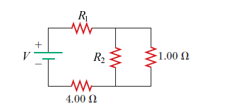
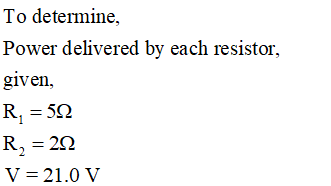
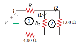
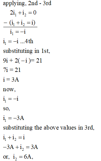
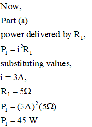
Calculate the power delivered to each resistor in the circuit shown in the figure below. (Let R1 = 5.00 Ω, R2 = 2.00 Ω, and V = 21.0 V.)
| resistor R1 | W |
| 4.00-ohm resistor | W |
| resistor R2 | W |
| 1.00-ohm resistor |

Step by step
Solved in 6 steps with 8 images


