RE lov-pans filtar vii 14 vi2 4046 V. MOR ID out VCO 11 12 Voc Figure 1: PLL circulit The PLL of Figure 1 is to be designed to have the following parameters: fmin = 6 kHz: fmax = 10 kHz: fp 1.5 kHz: CI 1.2 nF: Cf 11 nF. Assume the VCO characteristic fosc (Vo) is linear for OsVosV DD where VDD = 15 V and Vin(t) is a square wave signal at frequency fin For the PLL circuit of Figure 1, determine R1 (kilo-ohms): 2 What is the E24 standard value of R1 as determined in the preceding question (kilo-ohms): 2 For the PLL circuit of Figure 1, determine R2 (kilo-ohms): 2 What is the E24 standard value of R2 as determined in the preceding question (kilo-ohms): T.
RE lov-pans filtar vii 14 vi2 4046 V. MOR ID out VCO 11 12 Voc Figure 1: PLL circulit The PLL of Figure 1 is to be designed to have the following parameters: fmin = 6 kHz: fmax = 10 kHz: fp 1.5 kHz: CI 1.2 nF: Cf 11 nF. Assume the VCO characteristic fosc (Vo) is linear for OsVosV DD where VDD = 15 V and Vin(t) is a square wave signal at frequency fin For the PLL circuit of Figure 1, determine R1 (kilo-ohms): 2 What is the E24 standard value of R1 as determined in the preceding question (kilo-ohms): 2 For the PLL circuit of Figure 1, determine R2 (kilo-ohms): 2 What is the E24 standard value of R2 as determined in the preceding question (kilo-ohms): T.

Power System Analysis and Design (MindTap Course List)
6th Edition
ISBN:9781305632134
Author:J. Duncan Glover, Thomas Overbye, Mulukutla S. Sarma
Publisher:J. Duncan Glover, Thomas Overbye, Mulukutla S. Sarma
Chapter12: Power System Controls
Section: Chapter Questions
Problem 12.15P

Related questions
Question
Transcribed Image Text:RE
lov-pass filtar
vil 14
vi2
4046
KOR D
ki100k
out
VCO
in
3 11
12
Vosc
12
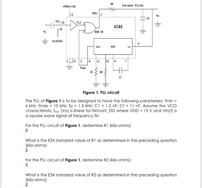
Figure 1: PLL circuit
The PLL of Figure 1 is to be designed to have the following parameters: fmin=
6 kHz; fmax = 10 kHz: fp 1.5 kHz: CI = 1.2 nF: Cf = 11 nF. Assume the VCO
characteristic fose (Vo) is linear for OsVosv DD where VDD = 15 V and Vin(t) is
a square wave signal at frequency fin
For the PLL circuit of Figure 1, determine R1 (kilo-ohms):
2
What is the E24 standard value of R1 as determined in the preceding question
(kilo-ohms):
2
For the PLL circuit of Figure 1, determine R2 (kilo-ohms):
2
What is the E24 standard value of R2 as determined in the preceding question
(kilo-ohms):
2
Expert Solution
This question has been solved!
Explore an expertly crafted, step-by-step solution for a thorough understanding of key concepts.

Step by step
Solved in 3 steps with 1 images

Recommended textbooks for you
Power System Analysis and Design (MindTap Course …
Electrical Engineering
ISBN:
9781305632134
Author:
J. Duncan Glover, Thomas Overbye, Mulukutla S. Sarma
Publisher:
Cengage Learning
Power System Analysis and Design (MindTap Course …
Electrical Engineering
ISBN:
9781305632134
Author:
J. Duncan Glover, Thomas Overbye, Mulukutla S. Sarma
Publisher:
Cengage Learning