Recall the echo system from the lecture notes in the section "Frequency response of LTI systems: Example D." In this problem, we will consider a different model for how an echo might be generated in a received signal. Specifically, we consider the model below, where T> 0 is a delay and a € (0, 1) is an attenuation factor: f(t). a 1 delay T seconds (a) As an example, suppose a = 0.5 and T = 2. Consider the input signal f(t) as shown below: f(t) 0 Plot the resulting output signal y(t). (b) Let's return to thinking about a and T as generic parameters, not associating them with specific values. In the time domain, we can write the input-output relationship of the echo system as follows: y(t) y(t) = f(t) + ay(t-T). Taking the Fourier transform of both sides of this equation, and using the time delay property of the Fourier transform, we can write Y(w) = F(w) + ???? - Y(w). Fill in the blanks in the equation above. (c) Rearranging terms in the equation above, we can write Y(w)(1-????) = F(w). Dividing Y(w) by F(w), we obtain H(w), the frequency response of the system: H(w)= Using your answer from part (b), find H(w). Y(w) F(w)
Recall the echo system from the lecture notes in the section "Frequency response of LTI systems: Example D." In this problem, we will consider a different model for how an echo might be generated in a received signal. Specifically, we consider the model below, where T> 0 is a delay and a € (0, 1) is an attenuation factor: f(t). a 1 delay T seconds (a) As an example, suppose a = 0.5 and T = 2. Consider the input signal f(t) as shown below: f(t) 0 Plot the resulting output signal y(t). (b) Let's return to thinking about a and T as generic parameters, not associating them with specific values. In the time domain, we can write the input-output relationship of the echo system as follows: y(t) y(t) = f(t) + ay(t-T). Taking the Fourier transform of both sides of this equation, and using the time delay property of the Fourier transform, we can write Y(w) = F(w) + ???? - Y(w). Fill in the blanks in the equation above. (c) Rearranging terms in the equation above, we can write Y(w)(1-????) = F(w). Dividing Y(w) by F(w), we obtain H(w), the frequency response of the system: H(w)= Using your answer from part (b), find H(w). Y(w) F(w)

Introductory Circuit Analysis (13th Edition)
13th Edition
ISBN:9780133923605
Author:Robert L. Boylestad
Publisher:Robert L. Boylestad
Chapter1: Introduction
Section: Chapter Questions
Problem 1P: Visit your local library (at school or home) and describe the extent to which it provides literature...

Related questions
Question
100%
Please help with answering this question and please write clearly and explain clearly, thanks.
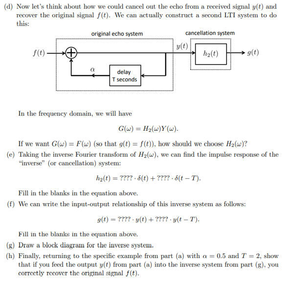
Transcribed Image Text:(d) Now let's think about how we could cancel out the echo from a received signal y(t) and
recover the original signal f(t). We can actually construct a second LTI system to do
this:
cancellation system
f(t)
original echo system
α
delay
T seconds
In the frequency domain, we will have
y(t)
h₂(t)
g(t)
G(w) = H₂(w)Y(w).
If we want G(w) = F(w) (so that g(t) = f(t)), how should we choose H₂(w)?
(e) Taking the inverse Fourier transform of H₂(w), we can find the impulse response of the
"inverse" (or cancellation) system:
h₂(t) = ???? 8(t) + ???? - 8(t – T).
Fill in the blanks in the equation above.
(f) We can write the input-output relationship of this inverse system as follows:
g(t) = ???? - y(t) + ???? - y(t – T).
Fill in the blanks in the equation above.
(g) Draw a block diagram for the inverse system.
(h) Finally, returning to the specific example from part (a) with a = 0.5 and T = 2, show
that if you feed the output y(t) from part (a) into the inverse system from part (g), you
correctly recover the original signal f(t).
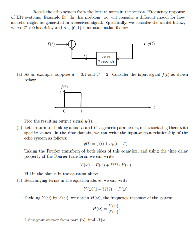
Transcribed Image Text:Recall the echo system from the lecture notes in the section "Frequency response
of LTI systems: Example D." In this problem, we will consider a different model for how
an echo might be generated in a received signal. Specifically, we consider the model below,
where T> 0 is a delay and a € (0, 1) is an attenuation factor:
f(t).
0
α
1
delay
T seconds
(a) As an example, suppose a = 0.5 and T = 2. Consider the input signal f(t) as shown
below:
f(t)
y(t)
Plot the resulting output signal y(t).
(b) Let's return to thinking about a and T as generic parameters, not associating them with
specific values. In the time domain, we can write the input-output relationship of the
echo system as follows:
t
y(t) = f(t) + ay(t-T).
Taking the Fourier transform of both sides of this equation, and using the time delay
property of the Fourier transform, we can write
Y(w) = F(w) + ???? .Y (w).
H(w) =
Using your answer from part (b), find H(w).
Fill in the blanks in the equation above.
(c) Rearranging terms in the equation above, we can write
Y(w) (1 - ????) = F(w).
Dividing Y(w) by F(w), we obtain H(w), the frequency response of the system:
Y(w)
F(w)
Expert Solution
This question has been solved!
Explore an expertly crafted, step-by-step solution for a thorough understanding of key concepts.

This is a popular solution!

Trending now
This is a popular solution!

Step by step
Solved in 5 steps with 3 images

Knowledge Booster


Learn more about
Need a deep-dive on the concept behind this application? Look no further. Learn more about this topic, electrical-engineering and related others by exploring similar questions and additional content below.Recommended textbooks for you
Introductory Circuit Analysis (13th Edition)
Electrical Engineering
ISBN:
9780133923605
Author:
Robert L. Boylestad
Publisher:
PEARSON

Delmar's Standard Textbook Of Electricity
Electrical Engineering
ISBN:
9781337900348
Author:
Stephen L. Herman
Publisher:
Cengage Learning

Programmable Logic Controllers
Electrical Engineering
ISBN:
9780073373843
Author:
Frank D. Petruzella
Publisher:
McGraw-Hill Education
Introductory Circuit Analysis (13th Edition)
Electrical Engineering
ISBN:
9780133923605
Author:
Robert L. Boylestad
Publisher:
PEARSON
Delmar's Standard Textbook Of Electricity
Electrical Engineering
ISBN:
9781337900348
Author:
Stephen L. Herman
Publisher:
Cengage Learning
Programmable Logic Controllers
Electrical Engineering
ISBN:
9780073373843
Author:
Frank D. Petruzella
Publisher:
McGraw-Hill Education

Fundamentals of Electric Circuits
Electrical Engineering
ISBN:
9780078028229
Author:
Charles K Alexander, Matthew Sadiku
Publisher:
McGraw-Hill Education

Electric Circuits. (11th Edition)
Electrical Engineering
ISBN:
9780134746968
Author:
James W. Nilsson, Susan Riedel
Publisher:
PEARSON

Engineering Electromagnetics
Electrical Engineering
ISBN:
9780078028151
Author:
Hayt, William H. (william Hart), Jr, BUCK, John A.
Publisher:
Mcgraw-hill Education,