Refrigerant HFC-134a as the working fluid Ideal cycle operation condition is assumed - Cycle is operated at high pressure line of 0.8 MPa - Cycle is operated at low temperature line of – 10° C Flow rate is 0.1 kg/sec The head of the department in the company that you are working in asked you to make use of pressure - enthalpy chart provided for HFC-134a refrigerant a. Construct didactic sketches, showing the operating principles of a refrigeration system
Refrigerant HFC-134a as the working fluid Ideal cycle operation condition is assumed - Cycle is operated at high pressure line of 0.8 MPa - Cycle is operated at low temperature line of – 10° C Flow rate is 0.1 kg/sec The head of the department in the company that you are working in asked you to make use of pressure - enthalpy chart provided for HFC-134a refrigerant a. Construct didactic sketches, showing the operating principles of a refrigeration system

Refrigeration and Air Conditioning Technology (MindTap Course List)
8th Edition
ISBN:9781305578296
Author:John Tomczyk, Eugene Silberstein, Bill Whitman, Bill Johnson
Publisher:John Tomczyk, Eugene Silberstein, Bill Whitman, Bill Johnson
Chapter50: Commercial, Packaged Rooftop, Variable Refrigerant Flow, And Variable Air Volume Systems
Section: Chapter Questions
Problem 18RQ: Explain how carbon dioxide levels can be used to estimate the occupancy level in a particular area...

Related questions
Question
Transcribed Image Text:Project 1
100
20.
150
200
250
300
350
400
450
500
550
600
650
CUPONTHFC-134a
700
200.
0.0016 1-
00018
10.
Pressure-Enthalpy
0.0014
000124
0.0020
8.
0.0030
100.
80.
6.
Diagram
volume-0.0040 mikg
(SI Units)
0.0060
0 0080
0.010
60.
40.
2.
0.015
0 020
20.
0030
0.8
0.040
10.
8.
0.6
0.060
0.4
6.
0 080
010
0.2
0.15
020
2.
0.1
0.08
0.30
0.40
1.
0.8
0.06
060
0.04
0.6
O80
1.0
0.4
0.02
1.5
20
0.2
0.01
100
150
200 250
300
350
400 450
0.1
700
500 550
600
650
Enthalpy (kJ/kg)
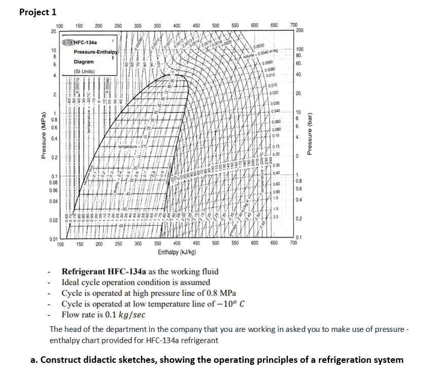
Refrigerant HFC-134a as the working fluid
- Ideal cycle operation condition is assumed
Cycle is operated at high pressure line of 0.8 MPa
Cycle is operated at low temperature line of – 10° C
- Flow rate is 0.1 kg/sec
The head of the department in the company that you are working in asked you to make use of pressure -
enthalpy chart provided for HFC-134a refrigerant
a. Construct didactic sketches, showing the operating principles of a refrigeration system
Pressure (bar)
4.
-Dozz -auneadu H
061 ta
091 Ti
1000
06 0
- --- 99'O
09
4.
Pressure (MPa)
Expert Solution
This question has been solved!
Explore an expertly crafted, step-by-step solution for a thorough understanding of key concepts.

Step by step
Solved in 2 steps with 1 images

Knowledge Booster


Learn more about
Need a deep-dive on the concept behind this application? Look no further. Learn more about this topic, mechanical-engineering and related others by exploring similar questions and additional content below.Recommended textbooks for you
Refrigeration and Air Conditioning Technology (Mi…
Mechanical Engineering
ISBN:
9781305578296
Author:
John Tomczyk, Eugene Silberstein, Bill Whitman, Bill Johnson
Publisher:
Cengage Learning
Refrigeration and Air Conditioning Technology (Mi…
Mechanical Engineering
ISBN:
9781305578296
Author:
John Tomczyk, Eugene Silberstein, Bill Whitman, Bill Johnson
Publisher:
Cengage Learning