Required information Consider the given figure. ā VA L₁ ell (b) (a) VB M L₁ 
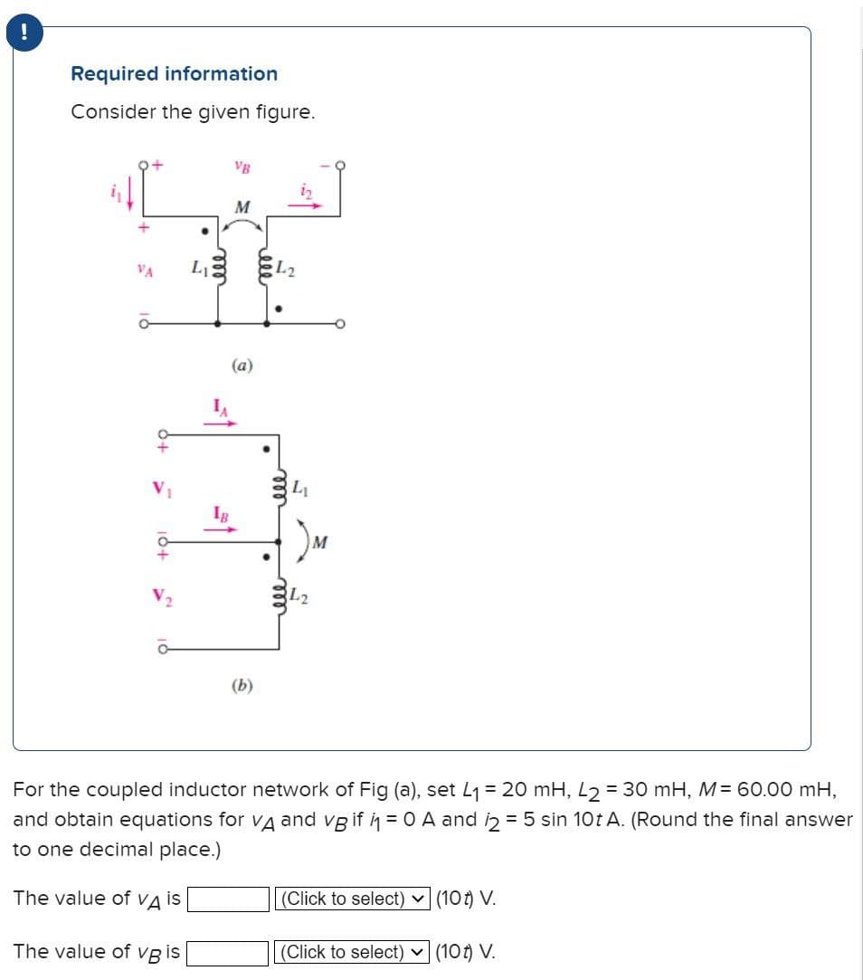
For the coupled inductor network of Fig (a), set 4₁ = 20 mH, L2 = 30 mH, M= 60.00 mH, and obtain equations for Vд and vg if i₁ = 0 A and 12 = 5 sin 10t A. (Round the final answer to one decimal place.) The value of VA is (Click to select) (10) V. The value of VB is (Click to select) ✓ (10) V.
Q: What is the value of the total current Is? Is 35 Ω 10V 210° ZT OI 5.0 223.8° A = OI, 0.164 223.8° A…
A: Given circuit:Find the total current Is
Q: Digital Signal Processing I Determine the period (c) FUIPAMENTAL FREQUENCY (w) AND CALCULATE FOURIER…
A: Since you have posted multiple questions, we will provide the solution only to the first question as…
Q: Prove that the following circle is unbalanced Wheatstone bridge, and How to R4 =110 Q and R3= 1900…
A: We are given,R1=480ΩR2=90ΩR3=190ΩR4=110Ωprove that the wheatstone bridge is unbalance and hou to…
Q: Write down the code table for the (7,4) multiplication cyclic code with generator polynomial g(p) =…
A: Cyclic codes are a class of linear block codes that possess the property of being cyclically…
Q: Q1) i) Write down an expression for the complex impedance Z1 viewed from the primary side of the…
A: Both parts of the given questions have been explained in detail . If any doubt please feel free to…
Q: Problem 3: A series LRC circuit has a resonant frequency of 6000 Hz. When it is driven at 8000 Hz,…
A: A series LRC circuit is a type of electrical circuit that contains three passive components…
Q: i need matlab code for Convert the transfer function to state space in Jordan canonical form of…
A: The given transfer function is shown below..It is asked to write the MATLAB code to convert the…
Q: The waveforms are correct for the logic circuit shown. ADC X A B C O True O False X
A: The logic circuit is given byThe waveforms are given byWe need to tell whether the given waveforms…
Q: Describe the operation of a diode and discuss its role in electrical circuits, including its…
A: A diode is a semiconductor device comprising a semiconductor material, which exhibits a predominant…
Q: "Implement the yellow highlighted table using multiplexers considering the digits used above (88 72…
A: According to the question, for the given table as shown belowWe need to implement the yellow…
Q: Draw a timing diagram for the D flip-flop figure and explain how you got the timing diagram.
A: The D flip flop,
Q: Show that AB + ABC + BC = AC + BC
A: The given data is shown below:
Q: INTLIC OF RESISTORS IN Voltages in the network. LEARNING ASSESSMENTS E2.17 Find V. in the network in…
A: Please refer below pages.If you have any questions feel free to ask.Explanation:Step 1: Step 2:
Q: What is the value of Thevenins impedance (ZTH) if VTH (the voltage between A and B) is 2 V
A: As you have asked only Thevenin impednce , so here is below. Thevnin impdance is : 1 Ohms *In…
Q: Att 0, a series - connected capacitor and inductor are placed across the terminals of a black box as…
A:
Q: find V1, V2, v3, V4 -j2 Ω 22-30° Α V 4 1-j3 Ω 3 Ω j2 Ω (+1 งา 2 6230° V 2-j Ω 2 Ω V 3
A: Given circuitwe use supernode analysis.
Q: Q2) Using Laplace Transform solve the following equation: (Simplify and pretty the solution) -2y"…
A: The given equation is shown below..We need to find the Laplace transform.Since the initial…
Q: 82) I8A 8342 K2 ми ΛΩ חי E 42\ Rh=?
A:
Q: Find I PRACTICE PROBLEM 9 30/0° V j4Q 502 -j30 892 150 www m 10 Ω -120
A: In this question, we need to determine the current in the circuit.
Q: Determine the nyquist rate (in rad/s) of the signal x(t) = sin (650πt) + sin (950πt)
A: The given data is shown below:
Q: Consider the circuit shown: V1 sine ✓ 60 Hz 120 Vrms ий 4:1 R1 100 Ω 1:2 Figure 2: Cascaded…
A: The circuit diagram,
Q: Vs, rms = 120v, f = 60Hz, vd = 250V Max power = 250 W, &s=100KHZ, C=440μF ~= 100m, Ld=lmH, R = 250…
A:
Q: For the electric circuit shown below, find i for >0 when the switch is open (as shown in the…
A: In the given question we need to calculate the current i flow through 12 ohm resistor.
Q: Write the mesh equations and solve for the mesh currents. Determine the voltage, V. XC R₂ HE w 202…
A: Mesh analysis is the combination of KVL and Ohm's law. KVL states that in any loop the algebraic sum…
Q: Find the Norton equivalent of the following circuit with respect to the terminals a and b. a) What…
A: Norton's Theorem states that any linear electrical network with multiple voltage and current sources…
Q: 4.4
A: VRMS = 3VExplanation:
Q: 2.16. Use Euler's relation to with the following functions in the form x(t) = A cos (wol + ).
A: x(t)=5cos(4πt+36.86) is the form of x(t)=Acos(w0t+ϕ) for given function…
Q: For the circuit below the switch has been closed a long time and opened at t=0. Find a. i(t) for t≥0…
A: The given circuit isWe need to determine the expressions of a. iL(t) for t≥0.b. i0(t) for t≥0+.c.…
Q: Find the mathematical expression for the wave form 1 Os <t<2s v(t) -5 2st< 3s 10<t<2 v(t): = -5…
A: Given waveform is,Asked to find the expression for the above waveform.
Q: 2. Calculate the output current io, where v = 1.4 V. 50 ΚΩ ww 10 ΚΩ +1 V1 ww 20 ΚΩ
A:
Q: Draw a circuit to realize each of the following expressions using AND gates, OR gates, and…
A: complete solution given belowExplanation:Thank you
Q: Using the methods discussed in this module, compute and plot the frequency content of this…
A: Given parameters maximum daily temperature (F)
Q: Find the Equilance resistance btw A & B R1 70 A o www BO ៥៩ 6Q m R3 12 Ω 122 mn
A: To calculate the equivalent resistance between A and B
Q: Given the circuit shown below, and the input signal, determine the output signal. Vi(t) + +1 + Vc(t)
A:
Q: Consider the system shown in Figure 1, where G(s) = a) If the unit step response of the closed-loop…
A: "Since you have posted a question with multiple sub parts, we will provide the solution only to the…
Q: 1. Draw the phasor-domain representation for the circuit below. 25 cos(4 10³t) V ! 1+ io 2 ΚΩ www 2!…
A: The circuit diagram,
Q: Full-wave 50 Hz sinusoidal controlled rectifier circuit with a peak voltage value of 100 and a…
A: Given:Peak voltage value (Vm) = 100 VSource inductance (L) = 8 mHLoad current (Iload) = 8 AFiring…
Q: As an engineer, and since taking over Hinckley power nuclear power plant, you are assigned to…
A: Designing a new Extra High Voltage (EHV) substation for distributing energy from Hinckley Point…
Q: Half-wave 50Hz sinusoidal uncontrolled rectifier circuit with a peak voltage value of 100V and a…
A: For a half-wave rectifier circuit,
Q: 10u(-t) V i(0+) = 302 0.25 H ww m v(0+) = di/dt (0+) = A/s dv/dt (0*) = V/s i(inf) = A v(inf) = V…
A:
Q: Q3. (a) Determine the flux crossing a 1mm x 1mm area on the surface of a cylindrical shell in Fig.…
A: (a) -4 uC(b) Meaning of negative answer is that flux lines are radially inwards pointing towards…
Q: 2.4.3 Find the current Iд in the circuit in Fig. P2.4.3.
A: The given data is shown below:
Q: Problem 7-4: Design a cascading LC low-pass filter with maximally flat magnitude response. Use a…
A: cut off frequencyDesigned the cascading LC low pass filter.
Q: Using Laplace transform, find io (t) for t>0. 4u(t)v+ 102 1F 1H 20 ww 102 e¹u(t)v io(t)
A: For the given circuit, it is asked to find the current io(t) for t>0 using Laplace transform
Q: 4.3
A: first option is correct.se the attachment for details.Explanation:
Q: (a) Given the network below, form an equivalent circuit for the transformer and primary, and use the…
A: The given data is shown below:
Q: 1- An 8-bit RTU microprocessor system with 6 channels can handle: A) 5 sensors B) 7 sensors C) 8…
A: In the given question we need to select the correct option among all the options.
Q: 10.7 Use nodal analysis to find V in the circuit of Fig. 10.56. 120 -15° V 40 Ω j200 V ww 6/30° A…
A: To analyze the network circuit and find the voltage or current through any component Kirchoff's law…
Q: The inductor L₁ in the circuit shown in Fig. P13.84 is carrying an initial current of p A at the…
A: The inductor L1 carry the initial current and inductor L1 current is i1 and inductor L2 current is…
Q: Example 7.28 In the RC circuit shown below, the capacitor has an initial charge qo = 2500 μC. At…
A:
Please answer in typing format
Step by step
Solved in 3 steps with 2 images
- Given a series circuit consisting of a DC voltage source, resistor, capacitor, inductor, and switch which closes at t=0. All elements are initially uncharged. If V=4 volts, R=64 Ohms, C=1/520 Farads, and L=8 Henries, Determine the circuit current (A,B,H,D): i(t)=Aexp(-Bt)sin(Ht+D) amps.The following parameters are used in an EDM process, the supply voltage is 150V. The resistance and capacitance in the circuit are 50 Ohms and 15 microfarads respectively. The tool is made of brass and kerosene is used as the dielectric. A hole diameter of 20 mm is to be cut into a plate of thickness of 3mm. If the discharge takes place at maximum power conditions. The value of constant K4=0.18, calculate the MRR, and machining time.A Maxwell bridge, designed to measure the unknown impedance (Ru, Lu) of a coil, isshown in Figure 7.8.(a) Derive an expression for Ru and Lu under balance conditions.(b) If the fixed bridge component values are R3 = 100 ohm and C =20 mF, calculatethe value of the unknown impedance if R1 = 3183 ohm and R2 = 50 ohm at balance.(c) Calculate the Q factor for the coil if the supply frequency is 50 Hz.
- A circuit element has the following voltage across it and current running through it.?(?) = 3 cos(100? + 30°) V,?(?) = 50sin(100? + 30°) mA.Assume polarities are chosen so that the current is flowing into the positive voltage terminal.(a) Determine if this circuit element is a resistor, capacitor, or inductor.(b) Find the impedance of this circuit element.(c) Find the component value of the circuit element. ie. if it is an resistor find R, if it is a capacitor, find C, if it is an inductor, find L.A three-conductor belted cable 15 mi long is used as a three-phase underground line for a 69 kV 50-Hz system. The cable common test results show that Ca= 0.15 µF/mi and C= 0.3 µF/mi. can you tell me what the 1. The capacitance of each phase to neutral in μF is 2. The total charging current in (A) 3. Conductor to sheath capacitance in (µF/mi) 4. Conductor to conductor capacitance in (µF) 5. If the first common test was performed on this cable, Ca is (uF/mi)Short Problem: Given a parallel RLC circuit comprised of the following element: 97.19-ohm resistor, ideal inductor with reactance of 36.14 ohms; and a capacitor with reactance of 16.25 ohms. Compute for true power in watts given an ac voltage source of 100 cis 0 volts. Note: Follow this reminder carefully. Compute to the nearest 4 decimal places. No Scientific notation. Do not round off in the middle of calculation. Use stored values. Write the numerical values only. No units in your final answer. Spaces are not allowed. Excessive number of decimals as compared to the required number of decimals may result to an incorrect answer.
- The following discrete time LTI system is, H(z)=: (i) (ii) (iii) (iv) 1 1-1.12+1.21z Causal if the system is stable Stable if the system is causal Causal if the system is not stable Stable if the system is not causal Choose the correct option. (a) Both (i) and (iv) are correct (b) Both (ii) and (iii) are correct (c) Both (i) and (ii) are correct (d) Both (i) and (iii) are correct Answer AShort Problem: Given a parallel RLC circuit comprised of the following element: 62.52-ohm resistor, ideal inductor with reactance of 33.15 ohms; and a capacitor with reactance of 6.11 ohms. Compute for true power in watts given an ac voltage source of 100 cis 0 volts. PLEASE ANSWER WITHIN 30 MINUTES. Round off to the nearest 4 decimal places. No Scientific notation. Do not round off in the middle of calculation. Use stored values. Write the numerical values only. No units in your final answer. Spaces are not allowed.Consider the load convention that is used for the RLC elements shown in Figure 2.2 of the text. A. If one says that an inductor absorbs zero real power and positive reactive power. is it (a) True (b) False B. If one says that a capacitor absorbs zero real power and negative reactive power (or delivers positive reactive power), is it (a) False (b) True C. If one says that a (positive-valued) resistor absorbs (positive) real power and zero reactive power, is it (a) True (b) False
- F.) A residential air conditioning unit with an SEER of 14 serves a single-detached family residence in Quezon City, Philippines having an annual cooling load hours of 6,116 hours. The total cooling load is 36,000 Btu/hr. Calculate the approximate annual energy consumption of the A/C unit.Two coupled coils have inductance of L1 = 0.8 H and L2 = 0.2 H, respectively. If the coefficient of coupling is 0.75, find the turns ratio N1/N2 for the coils. Show Solution PleaseFigure a shows the ignition circuit of an automobile system. It consists of four Resistors R, as well as the energy storing elements of Inductor and Capacitor . Meanwhile Figure b shows the equivalent circuit of the same system of Figure a. Let Z1 and Z2 be the Impedances seen from the respective terminals. The variables and are the mesh currents flowing in the loops 1 and 2, respectively. Let the values of Resistors are 2, while the value of the Capacitor and Inductor are 1. i) The total impedance of Z1=ii) The total impedance of Z2=iii) Current I2(S) in function of Vs(S) = iv} Find the transfer function of Vz2(S)/Vs(S) =