ro (which We RHOW in Vgs 9mVgs RG Vout RD Vin RS Vs Vin =Vgs + v, ndudingco Vout-Us 2 Vouu =ー8mR v, = 8mRsV gs -Comd imue V out G = Vin Vgs + 8mRsV es 1+ g„Rs The effect of Rs is to reduce the gain (undesirable). Detailed analysis shows that Rs develops negative feedback in the circuit, and phenomenon is called source degeneration. Sometimes it is employed deliberately in small amounts to make circuits more stable and resistant to component value variation. In the limit Rs → 0, then Gy = -gmRp as per the lecture notes. Numerically G, = -(1.72*5)/(1 + 1.72*6) = -0.76 NB - for gmRs >> 1, G, →Rp/Rs.
ro (which We RHOW in Vgs 9mVgs RG Vout RD Vin RS Vs Vin =Vgs + v, ndudingco Vout-Us 2 Vouu =ー8mR v, = 8mRsV gs -Comd imue V out G = Vin Vgs + 8mRsV es 1+ g„Rs The effect of Rs is to reduce the gain (undesirable). Detailed analysis shows that Rs develops negative feedback in the circuit, and phenomenon is called source degeneration. Sometimes it is employed deliberately in small amounts to make circuits more stable and resistant to component value variation. In the limit Rs → 0, then Gy = -gmRp as per the lecture notes. Numerically G, = -(1.72*5)/(1 + 1.72*6) = -0.76 NB - for gmRs >> 1, G, →Rp/Rs.

Introductory Circuit Analysis (13th Edition)
13th Edition
ISBN:9780133923605
Author:Robert L. Boylestad
Publisher:Robert L. Boylestad
Chapter1: Introduction
Section: Chapter Questions
Problem 1P: Visit your local library (at school or home) and describe the extent to which it provides literature...

Related questions

Question
Explain the answers
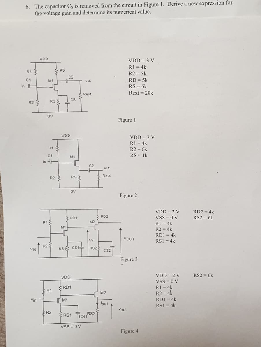
Transcribed Image Text:6. The capacitor Cs is removed from the circuit in Figure 1. Derive a new expression for
the voltage gaiìn and determine its numerical value.
VDD
VDD = 3 V
R1 = 4k
S RD
R1
R2 = 5k
C2
C1
M1
out
RD = 5k
in HH
RS = 6k
Rext 20k
Rext
Cs
R2
RS
ov
Figure 1
VDD
VDD = 3 V
R1 = 4k
R1 3
R2 = 6k
C1
RS = 1k
M1
in HE
C2
out
R2
RS
Rexd
ov
Figure 2
VDD = 2 V
VSS = 0 V
RD2 = 4k
RD1
RD2
RS2 = 6k
R12
M2
R1 = 4k
M1
R2 = 4k
RD1 = 4k
VOUT
V1
RS1 = 4k
VIN
R2
RS12 CS1=
RS2
Cs2
Figure 3
VDD = 2 V
RS2 = 6k
VDD
VSS = 0 V
RI = 4k
R2 = 4k
SRD1
R1
M2
Vin
M1
RD1 = 4k
but
RS1 = 4k
Vout
R2
{ RS1 Tcs RS2'
Vss = 0 V
Figure 4
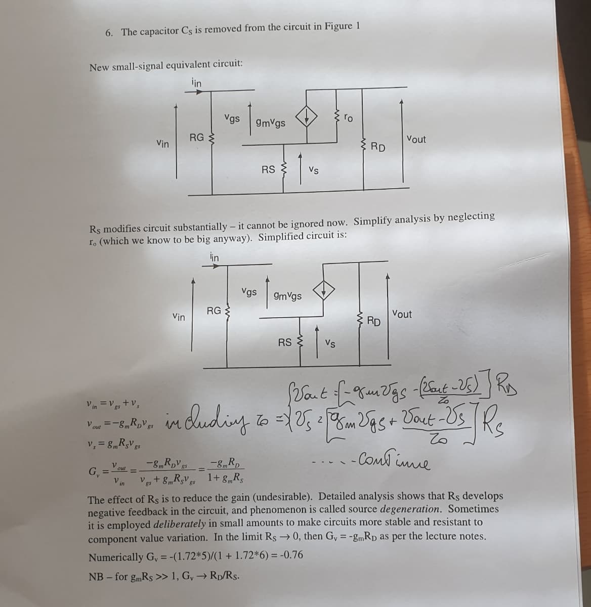
Transcribed Image Text:6. The capacitor Cs is removed from the circuit in Figure 1
New small-signal equivalent circuit:
iin
Vgs
gmVgs
RG
Vout
Vin
RD
RS
Vs
Rs modifies circuit substantially – it cannot be ignored now. Simplify analysis by neglecting
r. (which we know to be big anyway). Simplified circuit is:
lin
Vgs
9mVgs
RG
Vout
Vin
: RD
RS {
Vs
Vin =Vgs + v,
in dudiny to 05 m gs+ Dout -Us
Vout =-8mR,V gs
v, = 8mRsV gs
-Coml imue
Vout
G =
V in
%3D
Ves + 8mRsV es 1+ 8„Rs
The effect of Rs is to reduce the gain (undesirable). Detailed analysis shows that Rs develops
negative feedback in the circuit, and phenomenon is called source degeneration. Sometimes
it is employed deliberately in small amounts to make circuits more stable and resistant to
component value variation. In the limit Rs → 0, then Gy = -gmRp as per the lecture notes.
Numerically G, = -(1.72*5)/(1 + 1.72*6) = -0.76
NB – for gmRs >> 1, G, → Rp/Rs.
Expert Solution
This question has been solved!
Explore an expertly crafted, step-by-step solution for a thorough understanding of key concepts.

Step by step
Solved in 2 steps

Knowledge Booster


Learn more about
Need a deep-dive on the concept behind this application? Look no further. Learn more about this topic, electrical-engineering and related others by exploring similar questions and additional content below.Recommended textbooks for you
Introductory Circuit Analysis (13th Edition)
Electrical Engineering
ISBN:
9780133923605
Author:
Robert L. Boylestad
Publisher:
PEARSON

Delmar's Standard Textbook Of Electricity
Electrical Engineering
ISBN:
9781337900348
Author:
Stephen L. Herman
Publisher:
Cengage Learning

Programmable Logic Controllers
Electrical Engineering
ISBN:
9780073373843
Author:
Frank D. Petruzella
Publisher:
McGraw-Hill Education
Introductory Circuit Analysis (13th Edition)
Electrical Engineering
ISBN:
9780133923605
Author:
Robert L. Boylestad
Publisher:
PEARSON
Delmar's Standard Textbook Of Electricity
Electrical Engineering
ISBN:
9781337900348
Author:
Stephen L. Herman
Publisher:
Cengage Learning
Programmable Logic Controllers
Electrical Engineering
ISBN:
9780073373843
Author:
Frank D. Petruzella
Publisher:
McGraw-Hill Education

Fundamentals of Electric Circuits
Electrical Engineering
ISBN:
9780078028229
Author:
Charles K Alexander, Matthew Sadiku
Publisher:
McGraw-Hill Education

Electric Circuits. (11th Edition)
Electrical Engineering
ISBN:
9780134746968
Author:
James W. Nilsson, Susan Riedel
Publisher:
PEARSON

Engineering Electromagnetics
Electrical Engineering
ISBN:
9780078028151
Author:
Hayt, William H. (william Hart), Jr, BUCK, John A.
Publisher:
Mcgraw-hill Education,