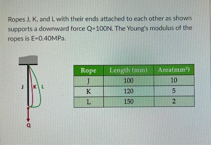
Ropes J, K, and L with their ends attached to each other as shown supports a downward force Q=100N. The Young's modulus of the ropes is E=0.40MPa. Rope Length (mm) Area(mm²) 10 J 100 J KL K 120 L 150 Q 52
Ropes J, K, and L with their ends attached to each other as shown supports a downward force Q=100N. The Young's modulus of the ropes is E=0.40MPa. Rope Length (mm) Area(mm²) 10 J 100 J KL K 120 L 150 Q 52

Mechanics of Materials (MindTap Course List)
9th Edition
ISBN:9781337093347
Author:Barry J. Goodno, James M. Gere
Publisher:Barry J. Goodno, James M. Gere
Chapter11: Columns
Section: Chapter Questions
Problem 11.5.10P: Solve the preceding problem (W 250 × 44.8) if the resultant force P equals 110 kN and E = 200 GPa.

Related questions

Question
1.Calculate the axial force in rope J in N.
2.Calculate the elongation in rope K in mm.
3.Calculate the normal stress in rope L in MPa.
Transcribed Image Text:Ropes J, K, and L with their ends attached to each other as shown
supports a downward force Q=100N. The Young's modulus of the
ropes is E=0.40MPa.
Rope Length (mm)
Area(mm²)
10
J
100
J
KL
120
150
KL
LO
5
2
Expert Solution
This question has been solved!
Explore an expertly crafted, step-by-step solution for a thorough understanding of key concepts.

Step by step
Solved in 3 steps with 3 images

Knowledge Booster


Learn more about
Need a deep-dive on the concept behind this application? Look no further. Learn more about this topic, mechanical-engineering and related others by exploring similar questions and additional content below.Recommended textbooks for you
Mechanics of Materials (MindTap Course List)
Mechanical Engineering
ISBN:
9781337093347
Author:
Barry J. Goodno, James M. Gere
Publisher:
Cengage Learning

International Edition---engineering Mechanics: St…
Mechanical Engineering
ISBN:
9781305501607
Author:
Andrew Pytel And Jaan Kiusalaas
Publisher:
CENGAGE L
Mechanics of Materials (MindTap Course List)
Mechanical Engineering
ISBN:
9781337093347
Author:
Barry J. Goodno, James M. Gere
Publisher:
Cengage Learning
International Edition---engineering Mechanics: St…
Mechanical Engineering
ISBN:
9781305501607
Author:
Andrew Pytel And Jaan Kiusalaas
Publisher:
CENGAGE L