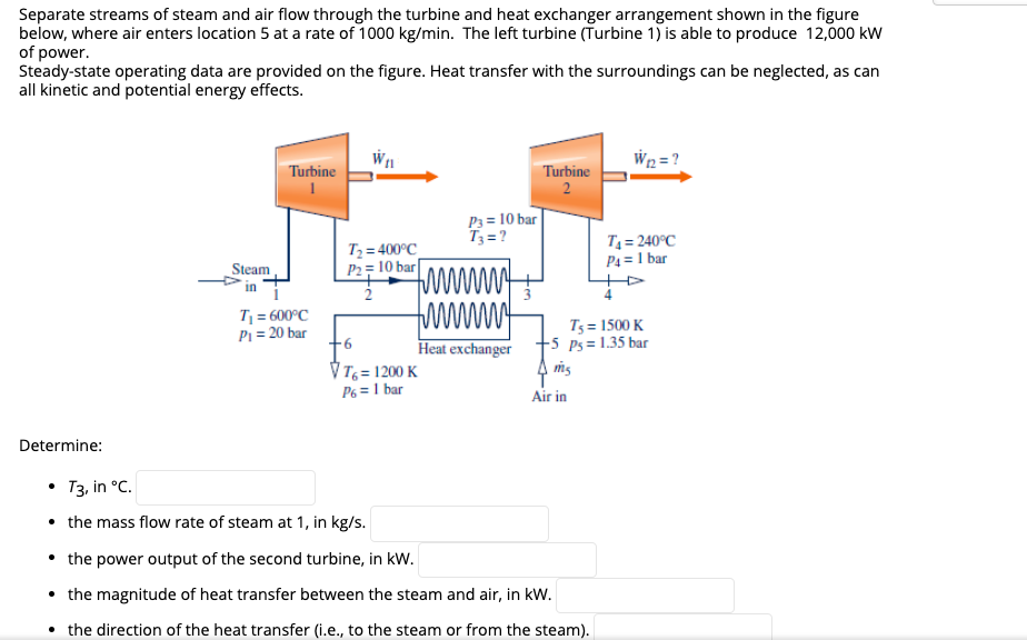
Separate streams of steam and air flow through the turbine and heat exchanger arrangement shown in the figure below, where air enters location 5 at a rate of 1000 kg/min. The left turbine (Turbine 1) is able to produce 12,000 kW of power. Steady-state operating data are provided on the figure. Heat transfer with the surroundings can be neglected, as can all kinetic and potential energy effects.
Separate streams of steam and air flow through the turbine and heat exchanger arrangement shown in the figure below, where air enters location 5 at a rate of 1000 kg/min. The left turbine (Turbine 1) is able to produce 12,000 kW of power. Steady-state operating data are provided on the figure. Heat transfer with the surroundings can be neglected, as can all kinetic and potential energy effects.

Principles of Heat Transfer (Activate Learning with these NEW titles from Engineering!)
8th Edition
ISBN:9781305387102
Author:Kreith, Frank; Manglik, Raj M.
Publisher:Kreith, Frank; Manglik, Raj M.
Chapter7: Forced Convection Inside Tubes And Ducts
Section: Chapter Questions
Problem 7.49P

Related questions

Concept explainers
Heat Exchangers
Heat exchangers are the types of equipment that are primarily employed to transfer the thermal energy from one fluid to another, provided that one of the fluids should be at a higher thermal energy content than the other fluid.
Heat Exchanger
The heat exchanger is a combination of two words ''Heat'' and ''Exchanger''. It is a mechanical device that is used to exchange heat energy between two fluids.
Question
100%
Transcribed Image Text:Separate streams of steam and air flow through the turbine and heat exchanger arrangement shown in the figure
below, where air enters location 5 at a rate of 1000 kg/min. The left turbine (Turbine 1) is able to produce 12,000 kW
of power.
Steady-state operating data are provided on the figure. Heat transfer with the surroundings can be neglected, as can
all kinetic and potential energy effects.
W2 = ?
Turbine
Turbine
2
P3 = 10 bar
T3 = ?
T2 = 400°C_
P2= 10 bar
T = 240°C
P4 = 1 bar
Steam
in
P1 = 20 bar
+6
T = 600°C
www
T5 = 1500 K
-5 Ps = 1.35 bar
Heat exchanger
V T = 1200 K
P6 = 1 bar
Air in
Determine:
T3, in °C.
• the mass flow rate of steam at 1, in kg/s.
• the power output of the second turbine, in kW.
• the magnitude of heat transfer between the steam and air, in kW.
• the direction of the heat transfer (i.e., to the steam or from the steam).
Expert Solution
This question has been solved!
Explore an expertly crafted, step-by-step solution for a thorough understanding of key concepts.

This is a popular solution!

Trending now
This is a popular solution!

Step by step
Solved in 4 steps with 3 images

Knowledge Booster


Learn more about
Need a deep-dive on the concept behind this application? Look no further. Learn more about this topic, mechanical-engineering and related others by exploring similar questions and additional content below.Recommended textbooks for you
Principles of Heat Transfer (Activate Learning wi…
Mechanical Engineering
ISBN:
9781305387102
Author:
Kreith, Frank; Manglik, Raj M.
Publisher:
Cengage Learning
Principles of Heat Transfer (Activate Learning wi…
Mechanical Engineering
ISBN:
9781305387102
Author:
Kreith, Frank; Manglik, Raj M.
Publisher:
Cengage Learning