Situation 1: Considering the truss shown in the figure, E = 200 GPa, Cross sectional area of all members is 3000 sq mm. The truss is loaded as follows: • 5 kN downward vertical loads acting at A. joints C, D, and E. • 10 kN horizontal load acting at joint F. • 20 kN vertical downward load acting at joint G. The truss is supported as follows: Pin support at point A • Roller support at Point H 5 kN 5kN VE 13 3 m 3m 5,KN D X ROH 3 m 3m 3m Jam 9m F 3 m 20 kN 1. Determine the vertical deflection at joint I. 2. Determine the vertical deflection at joint G. 3. Determine the horizontal deflection at point G. The beam is loaded as follows: 4. Determine the horizontal deflection at pint F. 5. If the vertical deflection at point G is limited to 10 mm only, what is the required cross- sectional area of all the members? Situation 2: Considering the frame shown in the figure below, E = 200 GPa, I = 2x10 mm² 8 kN/m 10 kN 4 m The beam is supported as follows: 3 m 3 m 20 kN Uniformly distributed vertical load of intensity 8 kN/m at member AB 20 kN point load acting 3m above the rocker support. Fixed support at point A Rocker support at Point C 6. Determine the vertical reaction at support A. 7. Determine the horizontal reaction at support 8. Determine the Moment reaction at support A. 9. Determine the vertical reaction at support C. 10. Determine the horizontal deflection of point C due to the loads with respect to its original location. Situation 3: Considering the fully restrained beam shown in Finuro 2 where F-200 CD₂ and 1-2x10² mm² M The beam is loaded as follows: Concentrated moment at a point 5 m. from the left support Load P inclined at angle G with respect to the horizontal, acting at 3 m. from the right support. The beam is supported as follows: • Fixed support at the left and right end. If P = 85 kN, M = 120 kNm, L = 14 m., and G = 30 degrees. 11. Determine the vertical reaction at support A. 12. Determine the horizontal reaction at support A. 13. Determine the Moment reaction at support A. 14. Determine the vertical reaction at support C. 15. Determine the horizontal reaction at support C. 16. Determine the Moment reaction at support C. 17. Determine the deflection at point B. 18. Determine the slope at point B.
Situation 1: Considering the truss shown in the figure, E = 200 GPa, Cross sectional area of all members is 3000 sq mm. The truss is loaded as follows: • 5 kN downward vertical loads acting at A. joints C, D, and E. • 10 kN horizontal load acting at joint F. • 20 kN vertical downward load acting at joint G. The truss is supported as follows: Pin support at point A • Roller support at Point H 5 kN 5kN VE 13 3 m 3m 5,KN D X ROH 3 m 3m 3m Jam 9m F 3 m 20 kN 1. Determine the vertical deflection at joint I. 2. Determine the vertical deflection at joint G. 3. Determine the horizontal deflection at point G. The beam is loaded as follows: 4. Determine the horizontal deflection at pint F. 5. If the vertical deflection at point G is limited to 10 mm only, what is the required cross- sectional area of all the members? Situation 2: Considering the frame shown in the figure below, E = 200 GPa, I = 2x10 mm² 8 kN/m 10 kN 4 m The beam is supported as follows: 3 m 3 m 20 kN Uniformly distributed vertical load of intensity 8 kN/m at member AB 20 kN point load acting 3m above the rocker support. Fixed support at point A Rocker support at Point C 6. Determine the vertical reaction at support A. 7. Determine the horizontal reaction at support 8. Determine the Moment reaction at support A. 9. Determine the vertical reaction at support C. 10. Determine the horizontal deflection of point C due to the loads with respect to its original location. Situation 3: Considering the fully restrained beam shown in Finuro 2 where F-200 CD₂ and 1-2x10² mm² M The beam is loaded as follows: Concentrated moment at a point 5 m. from the left support Load P inclined at angle G with respect to the horizontal, acting at 3 m. from the right support. The beam is supported as follows: • Fixed support at the left and right end. If P = 85 kN, M = 120 kNm, L = 14 m., and G = 30 degrees. 11. Determine the vertical reaction at support A. 12. Determine the horizontal reaction at support A. 13. Determine the Moment reaction at support A. 14. Determine the vertical reaction at support C. 15. Determine the horizontal reaction at support C. 16. Determine the Moment reaction at support C. 17. Determine the deflection at point B. 18. Determine the slope at point B.

Chapter2: Loads On Structures
Section: Chapter Questions
Problem 1P

Related questions

Question
Solve only six to ten ok just solve good correct Solutions Handwriting
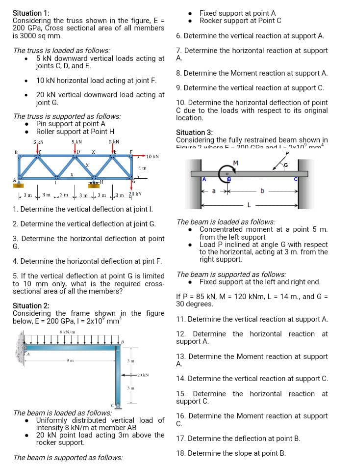
Transcribed Image Text:Situation 1:
Considering the truss shown in the figure, E =
200 GPa, Cross sectional area of all members
is 3000 sq mm.
The truss is loaded as follows:
•
5 kN downward vertical loads acting at
joints C, D, and E.
B
10 kN horizontal load acting at joint F.
• 20 kN vertical downward load acting at
joint G.
The truss is supported as follows:
Pin support at point A
Roller support at Point H
5 kN
5kN
VC
VE
43m 1 3
3 m
5.KN
D
3 m
X
143
X
X
POH
9m
3m 3m
4.3m
F
3 m 20 kN
1. Determine the vertical deflection at joint I.
2. Determine the vertical deflection at joint G.
3. Determine the horizontal deflection at point
G.
The beam is loaded as follows:
4. Determine the horizontal deflection at pint F.
5. If the vertical deflection at point G is limited
to 10 mm only, what is the required cross-
sectional area of all the members?
Situation 2:
Considering the frame shown in the figure
below, E = 200 GPa, I = 2x10³ mm²
8 kN/m
B
10 kN.
4 m
3 m
3m
20 KN
Uniformly distributed vertical load of
intensity 8 kN/m at member AB
• 20 kN point load acting 3m above the
rocker support.
The beam is supported as follows:
Fixed support at point A
Rocker support at Point C
6. Determine the vertical reaction at support A.
7. Determine the horizontal reaction at support
A.
8. Determine the Moment reaction at support A.
9. Determine the vertical reaction at support C.
10. Determine the horizontal deflection of point
C due to the loads with respect to its original
location.
Situation 3:
Considering the fully restrained beam shown in
Figure where F-200 CD₂ and 1 - 2v109 mm4
P
a
M
The beam is loaded as follows:
G
Concentrated moment at a point 5 m.
from the left support
Load P inclined at angle G with respect
to the horizontal, acting at 3 m. from the
right support.
The beam is supported as follows:
• Fixed support at the left and right end.
If P = 85 kN, M = 120 kNm, L = 14 m., and G =
30 degrees.
11. Determine the vertical reaction at support A.
12. Determine the horizontal reaction at
support A.
13. Determine the Moment reaction at support
A.
14. Determine the vertical reaction at support C.
15. Determine the horizontal reaction at
support C.
16. Determine the Moment reaction at support
C.
17. Determine the deflection at point B.
18. Determine the slope at point B.
Expert Solution
This question has been solved!
Explore an expertly crafted, step-by-step solution for a thorough understanding of key concepts.

Step by step
Solved in 4 steps with 5 images

Knowledge Booster


Learn more about
Need a deep-dive on the concept behind this application? Look no further. Learn more about this topic, civil-engineering and related others by exploring similar questions and additional content below.Recommended textbooks for you

Structural Analysis (10th Edition)
Civil Engineering
ISBN:
9780134610672
Author:
Russell C. Hibbeler
Publisher:
PEARSON

Principles of Foundation Engineering (MindTap Cou…
Civil Engineering
ISBN:
9781337705028
Author:
Braja M. Das, Nagaratnam Sivakugan
Publisher:
Cengage Learning
Structural Analysis (10th Edition)
Civil Engineering
ISBN:
9780134610672
Author:
Russell C. Hibbeler
Publisher:
PEARSON
Principles of Foundation Engineering (MindTap Cou…
Civil Engineering
ISBN:
9781337705028
Author:
Braja M. Das, Nagaratnam Sivakugan
Publisher:
Cengage Learning

Fundamentals of Structural Analysis
Civil Engineering
ISBN:
9780073398006
Author:
Kenneth M. Leet Emeritus, Chia-Ming Uang, Joel Lanning
Publisher:
McGraw-Hill Education


Traffic and Highway Engineering
Civil Engineering
ISBN:
9781305156241
Author:
Garber, Nicholas J.
Publisher:
Cengage Learning