Situation 3. The trame is loaded as ilustrated in Figure 3 and is hinged at point C. Sketch the shear, bending moment, and axial diagrams. Also draw the qualitative defiected shape as an overlay on the original frame. 15 KN/m 2m S0 N 80 AN 4 m 2.
Situation 3. The trame is loaded as ilustrated in Figure 3 and is hinged at point C. Sketch the shear, bending moment, and axial diagrams. Also draw the qualitative defiected shape as an overlay on the original frame. 15 KN/m 2m S0 N 80 AN 4 m 2.

Chapter2: Loads On Structures
Section: Chapter Questions
Problem 1P

Related questions

Question

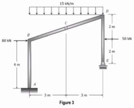
Transcribed Image Text:Situation 3. The trame is loaded as illustrated in Figure 3 and is hinged at point C. Sketch the shear, bending
moment, and axial diagrams. Also draw the qualitative deflected shape as an overlay on the original frame.
15 kN/m
2m
50 kN
80 AN
2 m
4 m
3 m
3m
Figure 3
Expert Solution
Step 1 Interpretation of data
Data given:
Asked:
- Sketch shear, Bending moment and Axial force diagram
Step 2 Primary calculations
Consider following free body diagram for given frame:
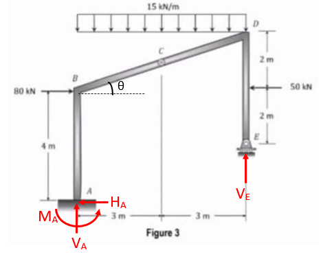
The angle can be obtained by,
Take summation of moment at C = 0,
Take ,
Finally, consider ,
In order to find Moment at A. let's again consider summation of moment at point C from left hand side,
Step 3 Calculations for axial force diagram
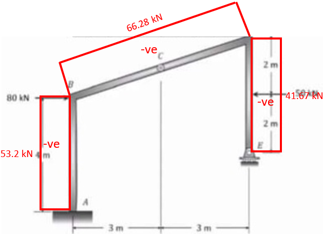
d

Step by step
Solved in 5 steps with 5 images

Knowledge Booster


Learn more about
Need a deep-dive on the concept behind this application? Look no further. Learn more about this topic, civil-engineering and related others by exploring similar questions and additional content below.Recommended textbooks for you

Structural Analysis (10th Edition)
Civil Engineering
ISBN:
9780134610672
Author:
Russell C. Hibbeler
Publisher:
PEARSON

Principles of Foundation Engineering (MindTap Cou…
Civil Engineering
ISBN:
9781337705028
Author:
Braja M. Das, Nagaratnam Sivakugan
Publisher:
Cengage Learning
Structural Analysis (10th Edition)
Civil Engineering
ISBN:
9780134610672
Author:
Russell C. Hibbeler
Publisher:
PEARSON
Principles of Foundation Engineering (MindTap Cou…
Civil Engineering
ISBN:
9781337705028
Author:
Braja M. Das, Nagaratnam Sivakugan
Publisher:
Cengage Learning

Fundamentals of Structural Analysis
Civil Engineering
ISBN:
9780073398006
Author:
Kenneth M. Leet Emeritus, Chia-Ming Uang, Joel Lanning
Publisher:
McGraw-Hill Education


Traffic and Highway Engineering
Civil Engineering
ISBN:
9781305156241
Author:
Garber, Nicholas J.
Publisher:
Cengage Learning