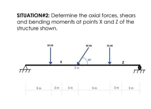
SITUATION#2: Determine the axial forces, shears and bending moments at points X and Z of the structure shown. so AN 2m 2m 2m


Q: Q4// Determine the shear force & bending moment for the beam shown below at C 60 N/m 400N 850 N.m…
A: Given:- The magnitude of the point load = 400 N The magnitude of the moment = 850 N.m The magnitude…
Q: Determine the shear force (V) in kN at point A for the beam as loaded in Figure 3.2b6. Given a = 3,…
A: Find reactions at the support:∑ Fy=0RA-[12×w4×b]=0RA=12×20×2RA=20kn
Q: 25 kN 5 kN 20 kN E 1 m 1 m 2 m 3 m
A: Draw FBD:
Q: The shear force diagram for an overhang beam supported at A and C as shown in the figure. Determine…
A:
Q: 2) Draw the shear force and bending moment diagrams using summation method. 50 kN 10 kN/m A -7 m -7…
A: Hi Thank you for the question . As per honour code we will answer the first question since exact one…
Q: 1. Plot the bending moment diagrams and shear force diagrams for the following structures. |4kN 3…
A: all questions are different type of problems so, i can solve problem 3.1 only
Q: Draw the load and the shear force diagrams that correspond to the given bending moment diagram. M…
A: Note: taking Moment at D 1520 kN.m as positive. Given data:
Q: -4 m A -4 m. $30° B 100 kN -4 m -4 m
A: Given- A cantilever beam carrying inclined load of 100kN making an angle of 30° with beam axis.…
Q: Question 2: Draw the diagrams of axial and shear forces as well as bending moment in the frame…
A: Given :- A frame is given with Point Load (P) = 200 KN and, Uniformly distributed load (q) = 50…
Q: Draw the shear, bending moment, and axial force diagrams and the qualitative deflected shape for the…
A: Solution: Draw the Free Body Diagram of the Frame Calculate the support reaction at the…
Q: Determine the expressions of V and M and draw the shear force and bending moment diagram for the…
A:
Q: 1. Analyze the beam shown at section 1 (determine the internal force; moment and shear). P (kN) 36…
A: Analyze the beam shown at section 1 (determine the internal force; moment and shear).
Q: Q1: For the beams and loadings shown, Draw the normal and shear force diagram. Draw the bending…
A:
Q: Determine the equations for shear and bending moment for the beam shown below. 37.5 kN/m 15 kN/m BO…
A:
Q: M(KN-m) 1,575 Draw the load and the shear force diagrams that correspond to the given bending moment…
A:
Q: 3 45 kN/m - 3 m - - 3 m - 3 m
A:
Q: 1.45 m 18.97 kN/m van 2.1 m 5 m 1.45 m
A:
Q: The beam carries various loadings as shown in the figure. An internal hinge is located at C.…
A: Given Beam a) To determine reactions b) To calculate resultant reaction force and and bending…
Q: H.W 1: For the beam shown in figure below, draw the axial, shear and bending moment diagrams. 25 kN…
A:
Q: 3. Draw the shear-force and bending-moment diagrams for the beam shown. Provide a detailed and…
A: Given data Find shear force and bending moment diagram.
Q: 1) Determine the shear force and bending moment diagrams for the depicted system. 26
A: Assume the value of b as 2m and the value of F as 5kN i.e., b = 2m F = 5kN
Q: Draw shear force and bending moment diagrams for the given simply supported beam.
A: Draw a free body diagram converting the UDL into a point loadAs UDL is given 5kn and it is acting on…
Q: Problem 1. Determine the axial forces, shears, and bending moments at points A and B of the…
A: Step:1 Determine support reactions about a structural axis.
Q: Determine the axial forces, shears, and bending moments at points A and B of the structure shown.
A: Given:- A structure is given with a two-point load The magnitude of the first point load = 45 kN…
Q: Draw the bending moment and shear force diagram for the beam in figure 1. 4 kN M = 2 kN-m B 2 m 2 m…
A:
Q: Determine the axial forces, shears, and bending moments at points A and B of the structures shown
A: GIVEN BEAM
Q: Problem 3: Draw the shear force and bending moment diagrams of the beam. 1000 lb/ft 6 ft 3 ft
A: Note:- Hi! Thank you for the question As per the honor code, We’ll answer the first question since…
Q: From the beam shown, determine the maximum shear force and maximum bending moment. 4KN/m 5KN/m 1m 4m…
A: Determine the support reactions. The following figure shows the Free Body Diagram of the beam. The…
Q: For the beam shown, derive the expressions for V and M, and draw the SHEAR FORCE and BENDING MOMENT…
A:
Q: Example (5): Draw the shear force and bending moment diagrams for the beam shown in Figure (2.13). 6…
A:
Q: For a timber double overhanging beam, the support conditions and loadings of the beam are shown in…
A: Consider the figure of the beam.
Q: determine the shear force and bending moment at point C in the figure. Given the details, Point 1 -…
A: It can be solved simply by considering section in span BC that moves from right to left so that…
Q: Draw shear force and Bending moment Diagram 8 kip 3 kip/ft A B 3 ft 5 ft 8 ft
A:
Q: For the beam shown, find the vertical shear at joint B. show your work 100 kN/m 60 kN/m 2.5 m 3.5 m
A:
Q: Determine the internal normal force, shear force, and bending moment at point C. 40 kN 8 kN/m 60° B…
A: In the design of structures or beams, In general, internal forces and moments are essential to…
Q: From the simply supported beam shown, determine the maximum shear force and maximum bending moment.…
A: "Hi! Thank you for the question. As per the honor code, We’ll answer the first question since the…
Q: 10 kips w= 5 kipw/ft 32 kip.ft D E.
A:
Q: H.W: Draw the axial force; shear force and bending moment diagrams for the frame shown below. 40 kN…
A:
Q: Determine the axial forces, shears, and bending moments at points A and B of the structure shown. 1.…
A: Consider the figure,
Q: 1. Determine the normal force, shear force, and moment at point C where A is pin support and B is…
A:
Q: Problem 1. Determine the axial forces, shears, and bending moments at points A and B of the…
A:
Q: 3 45 kN/m В 3 m 3 m 3 m 4-
A:
Q: Draw the shear force-bending moment diagram. 30 N 10 N 10 N/m В C D 1 m 1 m 1 m 3 m
A:
Q: Determine the internal axial force, shear force and bending moment at point C. calculate the…
A: From equalibrium,∑Fy = 0 ⇒ RA + RB = 10 + 1.8 + (8×0.8×sin30o) RA + RB = 15…
Q: 8 kN/m 12 kN • m A OB 5 m 3 m 4.
A:
Q: Analyze the given Frame 65KN 3m 3m B 18KN/m 5m 30KN/m 50° Analyze the strudure draw Shear, Axial and…
A: A construction, as it connects with structural designing, is an arrangement of interconnected…
Q: Problem 1. Determine the axial forces, shears, and bending moments at points A and B of the…
A:
Q: lok 2/ft 三 F 30kfb I 31 1,后1 21 21
A: The Given information is We have to calculate the Shear force and bending moment of the above…
Q: 12 ft A 12 ft B- 12 ft 4.5 k/ft y --
A: Given that:
Q: Determine the internal normal force, shear force, and bending moment acting at point C in the beam.…
A:

Step by step
Solved in 2 steps with 2 images

- Given both questions are subparts please give me both solutions. Which of the following gives the bending moment at point A on the beam shown (KN-m)? A. zero B. 895 C.1000 D.375 Which of the following gives the axial and shear force at point A on the beam, respectively(KN)? A. 45 and 66.667 B.75 and 91.667 C. 60 and 121.667 D. 75 and 283.333Use the graphical method to construct the shear-force and bending-moment diagrams for the beam shown. Let a = 7.5 m, b = 2.5 m, w = 27 kN/m, P = 44 kN, and MB = 67 kN·m. Label all significant points on each diagram and identify the maximum moments (both positive and negative) along with their respective locations. Clearly differentiate straight-line and curved portions of the diagrams. Determine the maximum shear force and bending moment in the beam.Note that answers may be positive or negative. Here, "maximum" refers to the largest magnitude value, but you should enter your shear force and bending moment with the correct sign, using the sign convention presented in Section 7.2 of the textbook. If the magnitudes of the largest positive and largest negative values are the same, enter a positive number.Use the graphical method to construct the shear-force and bending-moment diagrams for the beam shown. Let a = 8.7 m, b = 2.9 m, w = 29 kN/m, P = 69 kN, and MB = 51 kN·m. Label all significant points on each diagram and identify the maximum moments (both positive and negative) along with their respective locations. Clearly differentiate straight-line and curved portions of the diagrams. Determine the maximum shear force and bending moment in the beam. Note that answers may be positive or negative. Here, "maximum" refers to the largest magnitude value, but you should enter your shear force and bending moment with the correct sign, using the sign convention presented in Section 7.2 of the textbook. If the magnitudes of the largest positive and largest negative values are the same, enter a positive number.
- Use the graphical method to construct the shear-force and bending-moment diagrams for the beam shown. Let a = 1.1 m, b = 3.3 m, c = 2.2 m, P = 32 kN, and w = 29 kN/m. Label all significant points on each diagram and identify the maximum shear force and bending moment along with their respective locations. Clearly differentiate straight-line and curved portions of the diagrams.Note that answers may be positive or negative. Here, "maximum" refers to the largest magnitude value, but you should enter your shear force and bending moment with the correct sign, using the sign convention presented in Section 7.2 of the textbook. If the magnitudes of the largest positive and largest negative values are the same, enter a positive number.Use the graphical method to construct the shear-force and bending-moment diagrams for the beam shown. Let a = 1.3 m, b = 3.9 m, c = 2.6 m, P = 29 kN, and w = 34 kN/m. Label all significant points on each diagram and identify the maximum shear force and bending moment along with their respective locations. Clearly differentiate straight-line and curved portions of the diagrams. Note that answers may be positive or negative. Here, "maximum" refers to the largest magnitude value, but you should enter your shear force and bending moment with the correct sign, using the sign convention presented in Section 7.2 of the textbook. If the magnitudes of the largest positive and largest negative values are the same, enter a positive number.Use the graphical method to construct the shear-force and bending-moment diagrams for the beam shown. Let L= 11.5 m, MA = 86 kN-m, W = 22 kN/m, Mg = 40 kN-m. Label all significant points on each diagram and identify the maximum moments (both positive and negative) along with their respective locations. Clearly differentiate straight-line and curved portions of the diagrams. Determine the maximum shear force and bending moment in the beam. Note that answers may be positive or negative. Here, "maximum" refers to the largest magnitude value, but you should enter your shear force and bending moment with the correct sign, using the sign convention presented in Section 7.2 of the textbook. If the magnitudes of the largest positive and largest negative values are the same, enter a positive number.
- need help thnksss.... Calculate the shear force and bending moment by using shear-moment equationsmethod. Draw shear force and bending moment diagram. State all the principal values.Construct the Shear Force and Bending Moment Diagrams for the beam shown by the AREA METHOD, without writing the shear and moment equations. You are expected to draw neatly and accurately. Give all numerical values at all change of loading positions and at all points of zero shear. A) what is the value of R1 and R2 in kN? B) locate the point of zero shear from point A in meters? C) what is the maximum negative shear and maximum positive shear in kN? D) what is the bending moment (in kN-m) at point of zero shear? E) what is the maximum negative bending moment in kN-m? F) what is the shear force (in kN) and bending moment (in kN-m) located 3 meters from point A? G) what is the slope of the shear force on segment CD? I need it ASAP please. THANK YOUConstruct the Shear Force and Bending Moment Diagrams for the beam shown by the AREA METHOD, without writing the shear and moment equations. You are expected to draw neatly and accurately. Give all numerical values at all change of loading positions and at all points of zero shear. A) what is the value of R1 and R2 in kN? B) locate the point of zero shear from point A in meters? C) what is the maximum negative shear and maximum positive shear in kN? D) what is the bending moment (in kN-m) at point of zero shear? E) what is the maximum negative bending moment in kN-m? F) what is the shear force (in kN) and bending moment (in kN-m) located 3 meters from point A? G) what is the slope of the shear force on segment CD?
- sketch the shear, moment, and qualitative curve diagram for each member of the structure.Sketch the shear and bending moment diagrams for the beams below, indicating values ofshear force and bending moment at the key points. Use W = 100 N/m and L = 12 m.Use the graphical method to construct the shear-force and bending-moment diagrams for the beam shown. Let a = 2.0 m, b = 4.0 m, c = 2.7 m, P = 23 kN, w = 33 kN/m, and Q = 18 kN. Label all significant points on each diagram and identify the maximum shear force and bending moment along with their respective locations. Additionally:(a) Determine V and M in the beam at a point located 0.75 m to the right of B.(b) Determine V and M in the beam at a point located 1.10 m to the left of C.Note that answers may be positive or negative. Here, "maximum" refers to the largest magnitude value, but you should enter your shear force and bending moment with the correct sign, using the sign convention presented in Section 7.2 of the textbook. If the magnitudes of the largest positive and largest negative values are the same, enter a positive number.


