Solid and hollow shafts are most often used to provide power transmission of the rotating motion from the power source/engine to the car's wheels. In car manufacturing factory, your role is to determine the distribution of shear stress and the angular deflection due to predefined applied torsions to analyses and investigate the minimum and maximum stresses generated in the shafts. Considering the shaft in Figure.3, including a hollow part AB and solid part BC, your manger asked you to perform the following tasks: 1- determine the maximum and minimum shearing stress in shaft AB, giving that the outer diameter is 90 mm. 2- Sketch the distribution of the shear stress due to torsion in shaft AB. (simple sketch of shear stress “t" vs. shaft radius “p" for the elastic region) 3- Make a simple sketch the distribution of the angular deflection due to torsion in shaft AB. (simple sketch of torsion “T" vs. angle of twist “Q" for the elastic region) 4- Determine the required diameter of the solid shaft BC, if the allowable shearing stress is given as 75 MPa. 5- Sketch the distribution of the shear stress due to torsion in shaft BC. 6- Make a simple sketch to show the distribution of the angular deflection due to torsion in shaft BC.
Solid and hollow shafts are most often used to provide power transmission of the rotating motion from the power source/engine to the car's wheels. In car manufacturing factory, your role is to determine the distribution of shear stress and the angular deflection due to predefined applied torsions to analyses and investigate the minimum and maximum stresses generated in the shafts. Considering the shaft in Figure.3, including a hollow part AB and solid part BC, your manger asked you to perform the following tasks: 1- determine the maximum and minimum shearing stress in shaft AB, giving that the outer diameter is 90 mm. 2- Sketch the distribution of the shear stress due to torsion in shaft AB. (simple sketch of shear stress “t" vs. shaft radius “p" for the elastic region) 3- Make a simple sketch the distribution of the angular deflection due to torsion in shaft AB. (simple sketch of torsion “T" vs. angle of twist “Q" for the elastic region) 4- Determine the required diameter of the solid shaft BC, if the allowable shearing stress is given as 75 MPa. 5- Sketch the distribution of the shear stress due to torsion in shaft BC. 6- Make a simple sketch to show the distribution of the angular deflection due to torsion in shaft BC.

Chapter2: Loads On Structures
Section: Chapter Questions
Problem 1P

Related questions
Question
Answer 4/5/6
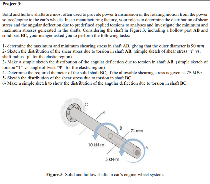
Transcribed Image Text:Project 3:
Solid and hollow shafts are most often used to provide power transmission of the rotating motion from the power
source/engine to the car's wheels. In car manufacturing factory, your role is to determine the distribution of shear
stress and the angular deflection due to predefined applied torsions to analyses and investigate the minimum and
maximum stresses generated in the shafts. Considering the shaft in Figure.3, including a hollow part AB and
solid part BC, your manger asked you to perform the following tasks:
1- determine the maximum and minimum shearing stress in shaft AB, giving that the outer diameter is 90 mm.
2- Sketch the distribution of the shear stress due to torsion in shaft AB. (simple sketch of shear stress “t" vs.
shaft radius "p" for the elastic region)
3- Make a simple sketch the distribution of the angular deflection due to torsion in shaft AB. (simple sketch of
torsion "T" vs. angle of twist “D" for the elastic region)
4- Determine the required diameter of the solid shaft BC, if the allowable shearing stress is given as 75 MPa.
5- Sketch the distribution of the shear stress due to torsion in shaft BC.
6- Make a simple sketch to show the distribution of the angular deflection due to torsion in shaft BC.
C
, 71 mm
10 kN-m
A
5 kN-m
Figure.3: Solid and hollow shafts in car's engine-wheel system.
B.
Expert Solution
This question has been solved!
Explore an expertly crafted, step-by-step solution for a thorough understanding of key concepts.

This is a popular solution!

Trending now
This is a popular solution!

Step by step
Solved in 4 steps with 3 images

Knowledge Booster


Learn more about
Need a deep-dive on the concept behind this application? Look no further. Learn more about this topic, civil-engineering and related others by exploring similar questions and additional content below.Recommended textbooks for you

Structural Analysis (10th Edition)
Civil Engineering
ISBN:
9780134610672
Author:
Russell C. Hibbeler
Publisher:
PEARSON

Principles of Foundation Engineering (MindTap Cou…
Civil Engineering
ISBN:
9781337705028
Author:
Braja M. Das, Nagaratnam Sivakugan
Publisher:
Cengage Learning
Structural Analysis (10th Edition)
Civil Engineering
ISBN:
9780134610672
Author:
Russell C. Hibbeler
Publisher:
PEARSON
Principles of Foundation Engineering (MindTap Cou…
Civil Engineering
ISBN:
9781337705028
Author:
Braja M. Das, Nagaratnam Sivakugan
Publisher:
Cengage Learning

Fundamentals of Structural Analysis
Civil Engineering
ISBN:
9780073398006
Author:
Kenneth M. Leet Emeritus, Chia-Ming Uang, Joel Lanning
Publisher:
McGraw-Hill Education


Traffic and Highway Engineering
Civil Engineering
ISBN:
9781305156241
Author:
Garber, Nicholas J.
Publisher:
Cengage Learning