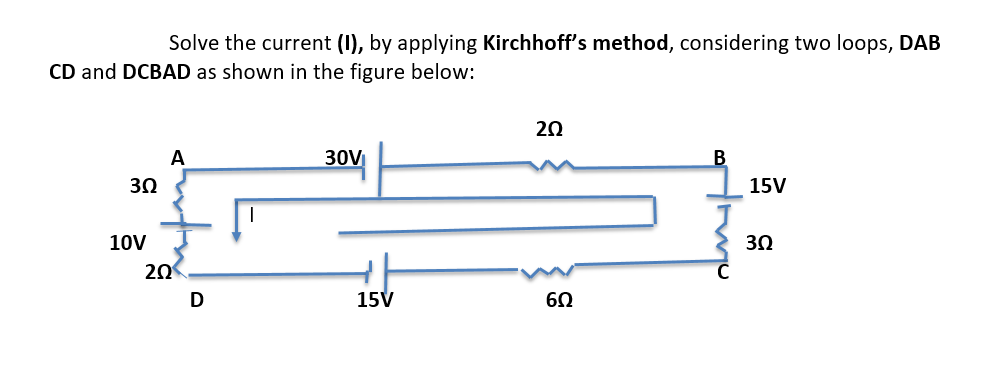
Solve the current (1), by applying Kirchhoff's method, considering two loops, DAB CD and DCBAD as shown in the figure below: 20 30V 3Ω 15V 10V 3Ω 20 D 15V 60


Q: 2. For the network shown, determine the following a.) IR IT IR IL| b.) IL XL 60 ohms R c.) IT 25…
A:
Q: For the given network below, determine the current through the 1-kn 1 kN - j4 kN + 6 V. 10 VZ 0° 2…
A:
Q: 8. Find IA in the circuit below by the use of superposition. Answer: Io = -1.67 mA 6V 2 kQ 2 mA 6 ka…
A:
Q: www 10Ω The electrical network shown can be viewed as consisting of three loops. Apply- ing…
A:
Q: 6. Find the current lo in the network below using Thevenin's Theorem 10 1220v V,07 j10 ll j10 le 10…
A: In this question, We need to calculate the current Io using the Thevenin theorems. Here one is…
Q: Q1) Use the sources conversions theorem to find the load current in the circuit s below 2A 30 Ω 20 2…
A:
Q: Problem (3) For the network shown in Figure below, find the current flowing in (12) resistor by…
A: ELECTRICAL NETWORK: When addressing a circuit problem or constructing a balanced circuit, the word…
Q: 2.42 50 2.6 2 In the circuit shown, determine the load currents I, and In + Rg RA 152 12 V 0.4 2 24…
A: In this question, Find the currents in all branches using the Superposition theorem. Here 2…
Q: For the circuit shown below, determine the minimum number equations required to calculate the loop's…
A: Minimum number equations required to calculate the loops equations?
Q: 4. Find Norton equivalent circuit across a and b terminals in the given circuit? 14 V 14 Ω 1A 6Ω 3 A…
A:
Q: For circuit shown below, assuming VBE = 0.7 V. Determine: (а) Іво (b) Vв (c) Ico
A: Since we only answer up to 3 sub-parts, we’ll answer the first 3. Please resubmit the question and…
Q: Practice Problem In the circuit shown, calculate the nodal voltages & V 2A V ww 20 0 10 n 4A
A: We will use the nodal analysis techniques to solve for node voltages. Please note that the given…
Q: Q1: Write mesh and nodal equations for the network shown in figurel ). R 2011 20n 200 R 2A Ry 18 0…
A: The nodes in electric circuits can be defined as the connecting point of different branches and…
Q: 5. Determine the mesh currents i, , i, and iz in the circuit belo 12V 20523 (4)6A
A:
Q: Determine the load currents at 20, 14 0, 4 0 and 100 Q using Superposition theorem. 2n3 14n 10n 5A
A:
Q: For the coupled circuit shown Fig.4. determine the values of currents I, and 12. 12 j10 Q j 20 2 25…
A:
Q: 1. For the circuit shown, find the current i. 2A 42 SA 20
A: Given circuit:
Q: Using the Norton theorem, referring to the series in Figure , determine : A) the Norton circuit B)…
A:
Q: The admittance for a circuit, G + jB, is 0.02 + j0.20. What is the impedance, R + jX? Provide…
A:
Q: 12 V Example 3 Given the information appearing in the network, determine: Ic (а) Iс RC RB (b) RC Vc…
A:
Q: Referring to the figure below. assume a 6V battery having a negligible resistance. to be connected…
A: (a) Current I from the first branch is, Eo-E=I×R122-6=I×0.5 I=232 A Current IB is,…
Q: 8 Ω 2V ΖΩ 4Ω Va 1 ЗА
A:
Q: CO3 3. A DC two-wire distribution line, 500m long and fed at one end is as shown in below circuit.…
A: In this question , two wire dc distribution line is given....We have to find voltage at point F with…
Q: 60mH 0.35: For the mutual electnc arcuit shown in figure beside if Vs=10cos100t Volts, write the set…
A: In this question, We need to write the mesh current equations of the given circuit?.
Q: For the circuit shown in the figure below, the value of currents I, and lz is: 1, R, = 30 Q R, = 602…
A: Given circuit,
Q: Q4: Using star delta transformation to transform delta (ABC) shown in figure 4 to star, then…
A:
Q: EXAMPLE 2 For the network shown in the Figure determine: a) Determine re. b) Determine Z¡, Zo and A,…
A:
Q: A 4000/400, to KVA trans former has R= 13 SL and (22= 0.15. The leakage reaetance referred to…
A: Given data, KVA rating S = 10 KVA. Voltage rating 4000/400 R1=13 Ω, R2=0.15 ΩX1'=45 ΩRm=6000 Ω,…
Q: 11.)Consider a PV Module with 4 solar PV cells with the Size of each 10cm x 10cm are connected in…
A:
Q: In the figure, the load absorbs 22.256 KVA at a power factor 0.544639 inductive. For the feeder…
A: The solution is given below
Q: QI) For the circuit shown in figure, use Nodal Analysis to obtain currents ir, iz and is. 40 ww 2A…
A:
Q: 1. a) A load takes 100kW at a power factor of 0.8 lagging. Calculate the apparent power and the…
A: The solution is as follows.
Q: Question #1 The circuit shown in Figure #1 consists of five impedances supplied by a similar number…
A: As per guidelines i have to answer first three sub parts.please post remaining again
Q: For the circuit diagram shown in Figure 4.8, determine the voltage V across the 5 N impedance and…
A:
Q: Use Kirchhoff's Laws to solve for the branch currents of the circuit shown below. 2 ko 4 kQ 3 ko 1…
A: Norton's Theorem-A linear RLC network containing more than one independent or dependent voltage…
Q: a) Determine the pole location of the system below b) Discuss the stability of the system and…
A: In this question, A control system is given Determine the pole of the system? And check the given…
Q: Impedance & Admittance Consider the following circuits in the questions below. Units are considered…
A: Impedance and admittance of given circuit Circuit 1 is inductive type Circuit 2 is capacitive type…
Q: • The number of loop currents required is 3. 10 Q 15Q 25 Q 200 50 • This time we will choose the…
A: According to the question we have to find the value of I1, I2, I3, I5ohm, I10ohm, I15ohm, I20ohm.
Q: Practice Problem In the circuit shown, calculate the nodal voltages & 2A V. ww 10 0 ww 20 0 50 4A
A:
Q: 222 RL 6v 442 222 332 Figure 2 6. Determine the current at the load laB in the given circuit in…
A:
Q: Q1// For the circuit shown Plot curve between V and I When voltage variable Vin 0.1 0.2 0.3 0.7 0.8…
A: Consider the given set of values for the input voltage and the circuit.
Q: 2Ω 10 Q 80
A:
Q: The system y(n)=x(3n)-2 is * Causal system O Static system None of the mentioned Non-causal system O…
A:
Q: 1. Given : 20 KVA ( instruments on Primary side) 2200/220 V SCT :V = 205 volts OCT: V = 220 volts…
A:
Q: Example 5.5 For the RL parallel circuit shown, E = 23040° V at 50 Hz, R = 115 Q and L = 0.366 H. E =…
A: Dear,as per company guidelines we can answer only 3 sub-parts at a time, kindly post other sub-parts…
Q: Find i₁0 for the given circuit below: www 2Ω 4Ω 12 V + 32 V ίγο 10 Ω
A: Given circuit,
Q: For the circuit shown, the following mesh currents are given: IA=1.92Z 2.10 A IB = 1.30Z -2.12 A Ic…
A: we need to determine the voltage VB.
Q: Assume that a primary feeder length L-8Km has a constant K = 0.008 (%VD/KVA.mil) and that a load…
A: Given thatLength of feeder L =8 kmConstant K = 0. 008 % VD/KVA. milLoad on feeder P = 100 KW power…
Q: Given: Pole, Y-connected IM R2=0.9 R2 = 0.91 X2 = 0.4 Frichon + Windage + Core Loss = 1,1006 160V,…
A: We are authorized to answer three subpart at a time, since you have not mentioned which question you…
Q: For the circuit shown, current I1 is: 12 V 52
A: Given : Brief description: In the above given question they have mentioned an electrical circuit…
Subject: Circuits

Step by step
Solved in 2 steps with 1 images

- Consider two interconnected voltage sources connected by a line of impedance Z=jX, as shown in Figure 2.27. (a) Obtain expressions for P12 and Q12. (b) Determine the maximum power transfer and the condition for it toGiven the complex numbers A1=630 and A2=4+j5, (a) convert A1 to rectangular form: (b) convert A2 to polar and exponential form: (c) calculate A3=(A1+A2), giving your answer in polar form: (d) calculate A4=A1A2, giving your answer in rectangular form: (e) calculate A5=A1/(A2*) giving your answer in exponential form.The real power delivered by a source to two impedances, Z1=4+j5 and Z2=10 connected in parallel, is 1000 W. Determine (a) the real power absorbed by each of the impedances and (b) the source current.
- Reconsider Problem 3.29. If Va,VbandVc are a negative-sequence set, how would the voltage and current relationships change? (a) If C1 is the complex positive-sequence voltage gain in Problem 3.29 and (b) if C2 is the negative sequence complex voltage gain, express the relationship between C1andC2a. Write the balancing equation for each loopwith clear explanation b. Then,write a matrix equation that determines the loop currents c. Solve the system for the loop currents.Show the complete and step-by-step solution for an upvote.
- solve for the dc quantities, VB(Q1), and VB(Q2)State Kirchhoff’s Current Law.For the system given below, a) Find K1 and K2 so that the steady-state error is zero, the settling time is one second, and the overshoot is 5% for a unit step input. b) Specify the system type and find the steady-state error a unit ramp input using the computed K1 and K2 values. "Can you explain step by step " check image "
- The swing equation provides the information about Stability of the system Efficiency of the system Power flow under steady state Performance of the systemDerive the equations below by using the circuits:Derive the full solution to the driven LRC circuit shown below using complex exponentials. Start withKirchhoff’s rule for the loop and assume a complex V (t) = V0eiωt (where by convention V0 is real) andassume that I(t) = I0eiωt where I0 is a general complex number (which can be written quite generallyas I0 = |I0|e−iδ), and where one gets physical answers at the end by taking the real part of thecomplex answers. Find an algebraic complex expression that expresses the sum of the voltages. Solve this expression directly using algebra, no pictures of “phasors” really required. Factor out the solution to obtain|I0|, δ, Z (the complex impedance), and the voltages across each element as a function of time.