Suppose the voltage waveform shown in Figure Q4a was observed at the sending end of a 50 Q transmission line in response to a step voltage introduced by a generator with V, =15 V and an unknown series (а) resistance, R . If the line is 1 km in length, velocity of propagation for the signals on the line is 1x10 m/s, and it is terminated in a load, Z, =100 N: %3D (i) Determine R, (ii) Explain why the drop in level of V (0,t) at t= 6us could only have been caused by a fault on the line and cannot be due to reflection from the load. (iii) Determine the location of the fault responsible for the observed waveform and the impedance R, at this location. V(0, t) 5 V- 3 V 6 μs
Suppose the voltage waveform shown in Figure Q4a was observed at the sending end of a 50 Q transmission line in response to a step voltage introduced by a generator with V, =15 V and an unknown series (а) resistance, R . If the line is 1 km in length, velocity of propagation for the signals on the line is 1x10 m/s, and it is terminated in a load, Z, =100 N: %3D (i) Determine R, (ii) Explain why the drop in level of V (0,t) at t= 6us could only have been caused by a fault on the line and cannot be due to reflection from the load. (iii) Determine the location of the fault responsible for the observed waveform and the impedance R, at this location. V(0, t) 5 V- 3 V 6 μs

Introductory Circuit Analysis (13th Edition)
13th Edition
ISBN:9780133923605
Author:Robert L. Boylestad
Publisher:Robert L. Boylestad
Chapter1: Introduction
Section: Chapter Questions
Problem 1P: Visit your local library (at school or home) and describe the extent to which it provides literature...

Related questions

Question
How did they come with this step?
Transcribed Image Text:Q4
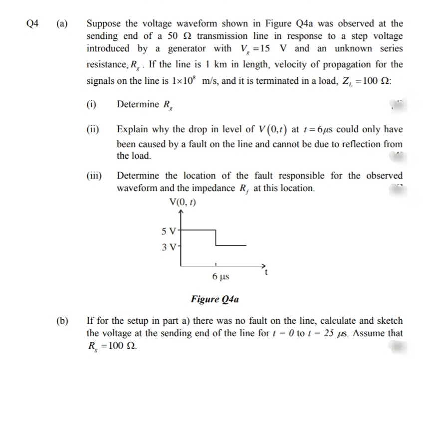
Suppose the voltage waveform shown in Figure Q4a was observed at the
sending end of a 50 N transmission line in response to a step voltage
introduced by a generator with V, =15 V and an unknown series
(а)
resistance, R. . If the line is 1 km in length, velocity of propagation for the
signals on the line is 1×10* m/s, and it is terminated in a load, Z, =100 N:
(i)
Determine R,
(ii)
Explain why the drop in level of V (0,t) at t=6µs could only have
been caused by a fault on the line and cannot be due to reflection from
the load.
(iii)
Determine the location of the fault responsible for the observed
waveform and the impedance R, at this location.
V(0, t)
5 V-
3 V
6 µs
Figure Q4a
If for the setup in part a) there was no fault on the line, calculate and sketch
the voltage at the sending end of the line for t = 0 to t = 25 µs. Assume that
R. =100 N.
(b)
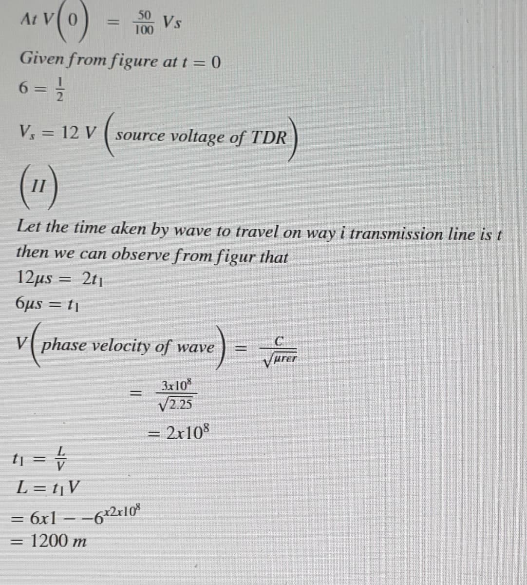
Transcribed Image Text:At
Vs
100
%3D
Given from figure at t = 0
6 = =
%3D
V = 12 V
source voltage of TDR
(1)
Let the time aken by wave to travel on way i transmission line is t
then we can observe from figur that
12μs -
2t1
6µs = tj
V phase velocity of wave
3x10
V2.25
%3D
= 2x10%
%3D
tj = =
L = t¡V
= 6x1 – -62r10*
1200 m
%3D
Expert Solution
This question has been solved!
Explore an expertly crafted, step-by-step solution for a thorough understanding of key concepts.

This is a popular solution!

Trending now
This is a popular solution!

Step by step
Solved in 4 steps with 3 images

Knowledge Booster


Learn more about
Need a deep-dive on the concept behind this application? Look no further. Learn more about this topic, electrical-engineering and related others by exploring similar questions and additional content below.Recommended textbooks for you
Introductory Circuit Analysis (13th Edition)
Electrical Engineering
ISBN:
9780133923605
Author:
Robert L. Boylestad
Publisher:
PEARSON

Delmar's Standard Textbook Of Electricity
Electrical Engineering
ISBN:
9781337900348
Author:
Stephen L. Herman
Publisher:
Cengage Learning

Programmable Logic Controllers
Electrical Engineering
ISBN:
9780073373843
Author:
Frank D. Petruzella
Publisher:
McGraw-Hill Education
Introductory Circuit Analysis (13th Edition)
Electrical Engineering
ISBN:
9780133923605
Author:
Robert L. Boylestad
Publisher:
PEARSON
Delmar's Standard Textbook Of Electricity
Electrical Engineering
ISBN:
9781337900348
Author:
Stephen L. Herman
Publisher:
Cengage Learning
Programmable Logic Controllers
Electrical Engineering
ISBN:
9780073373843
Author:
Frank D. Petruzella
Publisher:
McGraw-Hill Education

Fundamentals of Electric Circuits
Electrical Engineering
ISBN:
9780078028229
Author:
Charles K Alexander, Matthew Sadiku
Publisher:
McGraw-Hill Education

Electric Circuits. (11th Edition)
Electrical Engineering
ISBN:
9780134746968
Author:
James W. Nilsson, Susan Riedel
Publisher:
PEARSON

Engineering Electromagnetics
Electrical Engineering
ISBN:
9780078028151
Author:
Hayt, William H. (william Hart), Jr, BUCK, John A.
Publisher:
Mcgraw-hill Education,