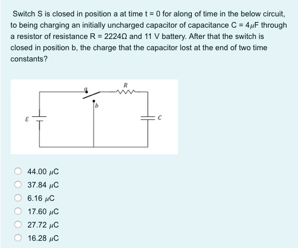
Switch S is closed in position a at time t = 0 for along of time in the below circuit, to being charging an initially uncharged capacitor of capacitance C = 4µF through a resistor of resistance R = 22240 and 11 V battery. After that the switch is closed in position b, the charge that the capacitor lost at the end of two time constants?
Q: Q2) For the circuit shown in Figure Q2, if each capacitor C has a value of 2 F, determine the total…
A: Apply the concept of capacitors in series and parallel,
Q: Consider the circuit shown in the figure. A short time after closing the switch, the charge on the…
A: Initially, the capacitor is fully charged. The capacitor discharges when the switch is open, the…
Q: Design a simple charging circuit using a 100 V source, a 1M resistor and a capacitor. The circuit…
A: The capacitor will not reach its final immediately after giving the input it will take five times…
Q: for t=2 s, find the energy stored in a 4 H inductor if the voltage across it is 24(1-e^-3). If the…
A:
Q: for t=2 s, find the energy stored in a 4 H inductor if the voltage across it is 24(1-e^-3). If the…
A:
Q: In the figure the capacitances are C, = 1.1 µF and C2 = 3.0 µF, and both capacitors are charged to a…
A: This probelm belongs to circuit theory . It is based on relationship in capacitor , voltage and…
Q: A 100-μF capacitor has a voltage given by v( t )=10−10 exp( −2t ) V. Find the power at t=0 and state…
A: Given: A capacitor whose capacitance and voltage across it is given by Formula and concept:
Q: Hays bridg
A: Hay's Bridge- These type of ac bridges are used to measure the unknown inductance applied in the…
Q: A certain parallel-plate capacitor consists of two plates, each with area 200 cm2, separated by a…
A: If two metal plates are connected across a battery, then due to the charges of plates an electric…
Q: In this problem you will calculate the inductance of an inductor from a current measurement taken at…
A:
Q: The capacitor in the circuit shown is charged to 20 V at the time the switch is closed. If the…
A: Given data: The voltage across capacitor is: 20 V The below circuit at t > 0, The value of…
Q: Derive the equivalent circuit for a parallel connection of ideal capacitors. Assume that the initial…
A: Parallel combination of capacitors is given in below figure, Current I is equal to,
Q: Suppose that we have a 1000-pF parallel-plate capacitor with air dielectric charged to 1000 V. The…
A: Stored energy of parallel plate capacitor charged to 1000 V is: If the plates are moved and…
Q: Capacitors in Figure Ql(a) has been charged up to its steady state condition. For each of the…
A:
Q: The figure below shows a simple RC circuit with a 3.50-µF capacitor, a 3.60-MQ resistor, a 9.00-V…
A: Note: Since we only answer up to 3 sub-parts, we’ll answer the first 3. Please resubmit the question…
Q: 8. Consider the series RC circuit below. C= 4.0mF %3D You? F1002 502 a. How should the open switch…
A: Since you have asked multiple questions in a single request, we will be answering only the first…
Q: Suppose that we have two 100-μF capacitors. One is charged to an initial voltage of 50 V, and the…
A: Given data, The value of capacitor C1 = 100 μF. The value of capacitor C2 = 100 μF. The value of…
Q: The circuit in the figure below has been connected for a long time. Let R1 = 7.80 Ω and R2 = 4.20…
A:
Q: A small capacitor of 100 pF is charged by a steady current of 1 µA for 1 ms. At that time, the…
A:
Q: An RC circuit includes a basic switch. In position "a", the battery, resistor and capacitor are…
A: “Since you have posted a question with multiple sub-parts, we will solve first three sub-parts for…
Q: Untufastresult.com C ELECTRICAL AND ELECTRONICS ENGINEERING (BEEE) 1 Prove that the energy stored in…
A: Given, R = 25ΩL = 64 mHC = 80μFV = 110 ∠0°f = 50 Hz Circuit diagram,
Q: A capacitor of capacity C is discharged through a resistance of value R. If the charge of this…
A:
Q: The switch below has been closed for a long period of time and is opened at t=0. a) Find the ENERGY…
A:
Q: In the figure R, = 4.00 N , and R, = 1.00 N. The inductor is ideal. When the switch is opened after…
A: The current in an inductor in a source free LR circuit is given by the formula :- I(t)=Ioe-RtLI(t)…
Q: The switch below has been closed for a long period of time and is opened at t=0. a) Find the ENERGY…
A: Since you have posted a question with multiple sub-parts, we will solve first three sub-parts for…
Q: 1. Design a capacitor set-up that can give at least 1 Farad. You can focus on the design by finding…
A: Note: We are authorized to answer one question at a time since you have not mentioned which question…
Q: R2 R3
A: In d.c. analysis, under steady state condition a capacitor will behave as OPEN CIRCUIT. The detailed…
Q: You are given 10 resistors that are each 30 Ω. Construct a circuit with a resistance of exactly 85…
A: Note : "Since you have posted a question with multiple sub-parts, we will solve first three…
Q: A capacitor is charged to a potential of 12.0 V and then connected to a voltmeter having an internal…
A: Given: Initial potential of capacitor V0=12 V Internal resistance of voltmeter R=3.4 MΩ At time t=4…
Q: PROBLEM 2: In the circuit shown, capacitor C1 has an initial charge qo = 300 x 10-6 Coulombs. If the…
A:
Q: An R-C series circuit consists of a capacitor with capacitance, C, connected in series with a…
A:
Q: For a resistor, what resistance corresponds to a short circuit? For an uncharged capacitor, what…
A: For short circuit, Resistor The expression of ohm's law is, V=IR, for short circuit V = 0…
Q: Consider the circuit below. The capacitor has a capacitance of 21 mF and starts out uncharged. The…
A: a) At time t=0, the switch is closed, the capacitor is replaced by short-circuit, the simplified…
Q: You find that a 25-µF capacitor connected to a 480 V AC is defective. The storeroom has no…
A: It is given that, The specifications of defective capacitor are, The capacitance of capacitor is,…
Q: v(t) (mV) 4 0.1 0.2 t(s) -2 Figure Q2(b)
A:
Q: In the figure R1 When the switch is opened after having been closed for a long time, the current in…
A: Given circuit is shown below. Given data is R1=4Ω, R2=1Ω. When switch is opened inductor current…
Q: A circuit is constructed with four resistors, one capacitor, one battery and a switch as shown. The…
A: “Since you have posted a question with multiple sub-parts, we will solve the first three sub-parts…
Q: 5. In the circuit shown in the figure, the switch S has been open for a long time and is suddenly…
A:
Q: 7. Find the voltages across the following components (a and b) after 1 second. The Capacitor is…
A: Here, we are given a circuit that consists of a series connection of a resistor (R) and a capacitor…
Q: Fill in the blanks add, capacitance, charge capacity, dielectric, dissipate, electrical circuits, ,…
A: The solution is as follows.
Q: Problem 4 The current through a 12-mH inductor is 4 sin 100t A. Find the voltage, across the…
A: Need to find energy and voltage
Q: Consider the circuit shown below. R1 = 100 N R, = 100 N C, = 10 mF V = 12 V R3 3 100 N C, = 4.7 mF…
A:
Q: The switch below has been closed for a long period of time and is opened at t=0. Switch_open_t=0 a)…
A: Since you have posted a question with multiple sub-parts, we will solve first three sub-parts for…
Q: large capacitor of 1000 μF is charged by a steady current of 1 mA until it reaches a voltage of 100…
A: To solve above question, one should understand the behavior of Inductor and capacitor in DC circuit.…
Q: 20-uF capacitor has a voltage of 5V across it at t=0. If a constant current of 30mA flows through…
A:
Q: 1. Equivalent Capacitance, Charge and Energy. Consider the circuit below. The capacitors are all…
A:
Q: What is the smallest number you could hook together to achieve your goal, and how would you connect…
A: (2)Given that,total capacitance CT=0.750 F=750 mFsingle capacitor value C=1.50 mFNow suppose we…
Step by step
Solved in 2 steps with 2 images
- 4. In what form is the energy of a capacitor stored?A capacitor uses air as a dielectric and has a capacitance of 3 F. A dielectric material is inserted between the plates without changing the spacing, and the capacitance becomes 15 F. What is the dielectric constant of this material?You are working in an industrial plant. You have been instructed to double the capacitance connected to a machine. The markings on the capacitor, however, are not visible. The capacitor is connected to 560 volts and an ammeter indicates a current of 6 amperes flowing to the capacitor. What size capacitor should be connected in parallel with the existing capacitor? What is the minimum AC voltage rating of the new capacitor? What is the minimum DC voltage rating of the new capacitor? What is the minimum KVAR size that can be used in this installation?
- A capacitor is made from two flat parallel plates placed 2 mm apart, .and its capacitance at vacuum is 10-12- F , if 200 volt applied in between then a Dielectric material was entered and its Dielectric constant Is 49 , Calculate : a) the new value of capacitance after the entrance of the Dielectric b) what is the value of charge on Dielectric material surface c) the polarization p of the Dielectric material d) calculate the displacement and the field inside the DielectricA ceramic capacitor is to be constructed to have a capacitance of 0.01µF and to have a steady working potential of 2.5 kV maximum. Allowing a safe value of field stress of 10 MV/m, determine (a) the required thickness of the ceramic dielectric, (b) the area of plate required if the relative permittivity of the ceramic is 10, and (c) the maximum energy stored by the capacitor.All capacitors were initially discharged. at t = 0, S1 is placed at position 1 and S2 is closed. At t = 15 ms, S1 is placed at position 2 and S2 is kept closed. During this phase, it has been determined that the total resistance seen by the equivalent capacitor is 28 kΩ; and that vT = 10 V at t = 15 ms. Calculate the value of the current iT immediately after the switching occurred. Enter your answer in mA rounded to 2 decimal places. At t = 25 ms, S1 is kept at position 2 and S2 is opened. Data: R1 = 6.5 kΩ, R2 = 10 kΩ, R3 = 1.0 kΩ, R4 = 4 kΩ, R5 = 20 kΩ, R6 = 11.5 kΩ; C1 = 4.5 µF, C2 = 4.0 µF, C3 = 12 µF
- An initially uncharged parallel plate capacitor is connected to a circuit containing a battery with emf &=48 V and a resistor, R=2.2MΩ as shown in the figure to below. The capacitor whose plates have an area of A=6.9 mm2 are separated by a distance of d=3.5 mm and one third of the capacitor is filled with a dielectric material, κ1=3.2 and the rest (two thirds) is filled with another dielectric material, κ2=6.5. At t=0 the switch is closed 2.7 seconds after the switch is closed the electric. field within the first dielectric material (κ1) is observed to be 6×10³ N/C. Find the potential difference across the capacitor at this instant (t=2.7 s) in terms of permitivity of free spaceϵ? Express your answer using zero decimal place.A capacitor with parallel plates, of area A and separation 2a, is connected to a potential difference ∆V. Then a conductive metal plate of area is introduced A / 2 and thickness a up to the middle of the capacitor (red in the figure). Finally it is introduced an insulating material of dielectric constant κ in the second half (blue in the figure), with equal area and thickness as conductive material. Find The capacity and accumulated energy when the capacitor is empty.Between the plates of a capacitor with an area of A = 40 cm², and distance between the plates of d = 30 cm, three dielectric materials are placed, as shown in the following figure. what is the equivalent capacitance of the capacitor with the three dielectric materials with permittivities ε1= 0.20 F / m, ε2=0.30 F / m, ε3= 0.40 F / m ? a) 3,7mF b) 6,7mF c) 9,7mF d)10mF e)none of the alternatives
- A paper dielectric plate capacitor is to be experimentally tested. The metal plates and the paper material between said plates are all 20 cm in radius and subjected to 10V dc in the test. How much is the capacitance does this capacitor have in picofarads (pF), if the paper material between plates used is 2 cm thick? Input answer in 4 decimal places and in pF. Note: Relative permittivity of the paper ( εr ) : 0.4225An RC circuit (see Figure 4) contains a resistor (10 ohms) anda capacitor (0.2 F) linked in series with an electromotiveforce E(t) = 10 sin 2πt.(a) Use a numerical solver to sketch the graph of thecharge on the capacitor versus time for each of theinitial conditions Q(0) = −1, −0.75, −0.5,..., 1 onthe time interval [0, 15]. What appears to happen toeach of the solutions with the passage of time? Explain what might be meant by a steady-state response.(b) What is the frequency of the emf? What appears to bethe frequency of the steady-state response? Hint: Recall that in the function f (t) = sin ωt, ω is called theangular frequency, the period is given by T = 2π/ω,and the frequency is the reciprocal of the period.Think of the frequency as the number of cycles persecond, a unit known as Hertz (Hz).5 Assume that you have been tasked with evaluating a new inductor. The inductor has a Q of 1454 at 50KHZ; a 0.1mm diameter, and is fabricated by wrapping a 10meter length copper wire wound around a magnetic core. Assume the following parameters for copper wire wound around a magnetic permeability of copper is 1. A. what is the inductance of the inductor? B. Assuming that the skin affect does not affect the Q at 50KHZ at all, determine the Q at 50MHZ.