Table 1 Gray Decimal Binary 0000 0000 1 0001 0001 86 0011 0010 3 0010 0011 4 0110 0100 5 0111 0101 6. 0101 0110 7 0100 0111 8 1100 1000 10 9 1101 1001 10 1111 1010 12 11 1110 1011 13 12 1010 1100 13 1011 1101 Figure. 1 XOR chip74-86 14 1001 1110 15 1000 1111
Table 1 Gray Decimal Binary 0000 0000 1 0001 0001 86 0011 0010 3 0010 0011 4 0110 0100 5 0111 0101 6. 0101 0110 7 0100 0111 8 1100 1000 10 9 1101 1001 10 1111 1010 12 11 1110 1011 13 12 1010 1100 13 1011 1101 Figure. 1 XOR chip74-86 14 1001 1110 15 1000 1111

Chapter22: Sequence Control
Section: Chapter Questions
Problem 6SQ: Draw a symbol for a solid-state logic element AND.

Related questions
Question
100%
Please can you help me
And solve this problem
I hope it includes a solution the k-map and logic circuit diagram
Transcribed Image Text:Table
Gray
Binary
Decimal
0000
0000
1
0001
0001
86
0011
0010
1
3
0010
0011
2
4
0110
0100
5
0111
0101
0101
0110
7
0100
0111
8.
1100
1000
10
1101
1001
10
1111
1010
12
11
1110
1011
13
12
1010
1100
13
1011
1101
Figure. 1 XOR chip74-86
14
1001
1110
15
1000
1111
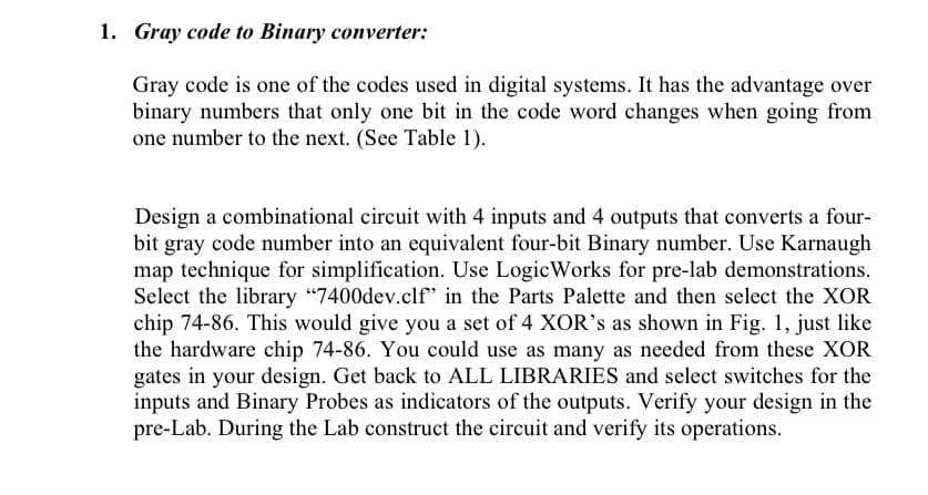
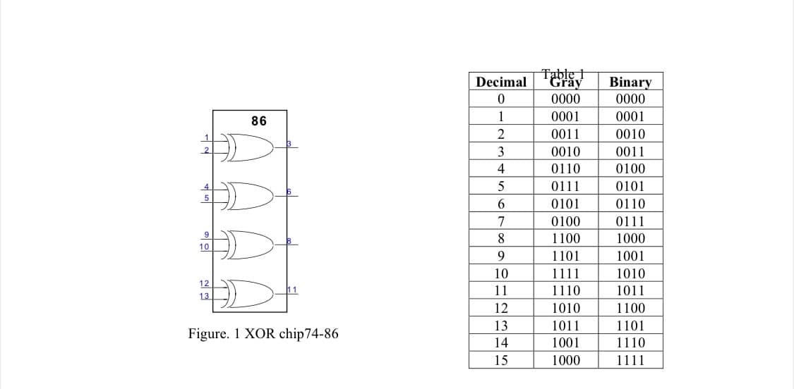
Transcribed Image Text:1. Gray code to Binary converter:
Gray code is one of the codes used in digital systems. It has the advantage over
binary numbers that only one bit in the code word changes when going from
one number to the next. (See Table 1).
Design a combinational circuit with 4 inputs and 4 outputs that converts a four-
bit gray code number into an equivalent four-bit Binary number. Use Karnaugh
map technique for simplification. Use LogicWorks for pre-lab demonstrations.
Select the library "7400dev.clf" in the Parts Palette and then select the XOR
chip 74-86. This would give you a set of 4 XOR's as shown in Fig. 1, just like
the hardware chip 74-86. You could use as many as needed from these XOR
gates in your design. Get back to ALL LIBRARIES and select switches for the
inputs and Binary Probes as indicators of the outputs. Verify your design in the
pre-Lab. During the Lab construct the circuit and verify its operations.
Expert Solution
This question has been solved!
Explore an expertly crafted, step-by-step solution for a thorough understanding of key concepts.

Step by step
Solved in 4 steps with 7 images

Knowledge Booster


Learn more about
Need a deep-dive on the concept behind this application? Look no further. Learn more about this topic, electrical-engineering and related others by exploring similar questions and additional content below.Recommended textbooks for you