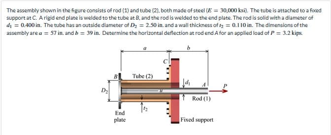
The assembly shown in the figure consists of rod (1) and tube (2), both made of steel (E = 30,000 ksi). The tube is attached to a fixed support at C. A rigid end plate is welded to the tube at B, and the rod is welded to the end plate. The rod is solid with a diameter of d₁ = 0.400 in. The tube has an outside diameter of D₂ = 2.50 in. and a wall thickness of 1₂ = 0.110 in. The dimensions of the assembly are a = 57 in. and b = 39 in. Determine the horizontal deflection at rod end A for an applied load of P = 3.2 kips. End plate Tube (2) Jd₁ Rod (1) Fixed support
The assembly shown in the figure consists of rod (1) and tube (2), both made of steel (E = 30,000 ksi). The tube is attached to a fixed support at C. A rigid end plate is welded to the tube at B, and the rod is welded to the end plate. The rod is solid with a diameter of d₁ = 0.400 in. The tube has an outside diameter of D₂ = 2.50 in. and a wall thickness of 1₂ = 0.110 in. The dimensions of the assembly are a = 57 in. and b = 39 in. Determine the horizontal deflection at rod end A for an applied load of P = 3.2 kips. End plate Tube (2) Jd₁ Rod (1) Fixed support

Mechanics of Materials (MindTap Course List)
9th Edition
ISBN:9781337093347
Author:Barry J. Goodno, James M. Gere
Publisher:Barry J. Goodno, James M. Gere
Chapter2: Axially Loaded Members
Section: Chapter Questions
Problem 2.4.1P: The assembly shown in the figure consists of a brass core (diameter d:= 0.25 in.) surrounded by a...

Related questions
Question
Transcribed Image Text:The assembly shown in the figure consists of rod (1) and tube (2), both made of steel (E = 30,000 ksi). The tube is attached to a fixed
support at C. A rigid end plate is welded to the tube at B, and the rod is welded to the end plate. The rod is solid with a diameter of
d₁ = 0.400 in. The tube has an outside diameter of D₂ = 2.50 in. and a wall thickness of 12 = 0.110 in. The dimensions of the
assembly are a = 57 in. and b = 39 in. Determine the horizontal deflection at rod end A for an applied load of P = 3.2 kips.
b
End
plate
Tube (2)
↑ Rod (1)
Fixed:
support
Expert Solution
This question has been solved!
Explore an expertly crafted, step-by-step solution for a thorough understanding of key concepts.

This is a popular solution!

Trending now
This is a popular solution!

Step by step
Solved in 4 steps with 4 images

Knowledge Booster


Learn more about
Need a deep-dive on the concept behind this application? Look no further. Learn more about this topic, mechanical-engineering and related others by exploring similar questions and additional content below.Recommended textbooks for you
Mechanics of Materials (MindTap Course List)
Mechanical Engineering
ISBN:
9781337093347
Author:
Barry J. Goodno, James M. Gere
Publisher:
Cengage Learning
Mechanics of Materials (MindTap Course List)
Mechanical Engineering
ISBN:
9781337093347
Author:
Barry J. Goodno, James M. Gere
Publisher:
Cengage Learning