The beam shown below is subjected to a point load of 10kN and a uniformly distributed load of 3kN/m, and is supported at A by a
The beam shown below is subjected to a point load of 10kN and a uniformly distributed load of 3kN/m, and is supported at A by a

Mechanics of Materials (MindTap Course List)
9th Edition
ISBN:9781337093347
Author:Barry J. Goodno, James M. Gere
Publisher:Barry J. Goodno, James M. Gere
Chapter10: Statically Indeterminate Beams
Section: Chapter Questions
Problem 10.3.2P: A fixed-end b earn is subjected to a point load at mid-span. The beam has a rectangular cross...

Related questions
Question
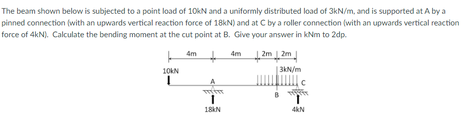
Transcribed Image Text:The beam shown below is subjected to a point load of 10kN and a uniformly distributed load of 3kN/m, and is supported at A by a
pinned connection (with an upwards vertical reaction force of 18KN) and at C by a roller connection (with an upwards vertical reaction
force of 4kN). Calculate the bending moment at the cut point at B. Give your answer in kNm to 2dp.
4m
to
4m
2m | 2m
10kN
| 3kN/m
A
18kN
4kN
Expert Solution
This question has been solved!
Explore an expertly crafted, step-by-step solution for a thorough understanding of key concepts.

This is a popular solution!

Trending now
This is a popular solution!

Step by step
Solved in 2 steps with 2 images

Knowledge Booster


Learn more about
Need a deep-dive on the concept behind this application? Look no further. Learn more about this topic, mechanical-engineering and related others by exploring similar questions and additional content below.Recommended textbooks for you
Mechanics of Materials (MindTap Course List)
Mechanical Engineering
ISBN:
9781337093347
Author:
Barry J. Goodno, James M. Gere
Publisher:
Cengage Learning

International Edition---engineering Mechanics: St…
Mechanical Engineering
ISBN:
9781305501607
Author:
Andrew Pytel And Jaan Kiusalaas
Publisher:
CENGAGE L
Mechanics of Materials (MindTap Course List)
Mechanical Engineering
ISBN:
9781337093347
Author:
Barry J. Goodno, James M. Gere
Publisher:
Cengage Learning
International Edition---engineering Mechanics: St…
Mechanical Engineering
ISBN:
9781305501607
Author:
Andrew Pytel And Jaan Kiusalaas
Publisher:
CENGAGE L