The circuit below, you may note, does not match any of the common op-amp circuits. By performing circuit analysis, determine the voltage across the load resistor R5. You may assume that V1 = 5.1 V, V2 = 4.2 V, R1 = 95 kQ, R2 = 63 KQ, R3 = 40 kQ, R4 = 28 kQ, and R5 = 73 kQ. R1 V1 R2 V2 + + R3 R4 R5 mn m
The circuit below, you may note, does not match any of the common op-amp circuits. By performing circuit analysis, determine the voltage across the load resistor R5. You may assume that V1 = 5.1 V, V2 = 4.2 V, R1 = 95 kQ, R2 = 63 KQ, R3 = 40 kQ, R4 = 28 kQ, and R5 = 73 kQ. R1 V1 R2 V2 + + R3 R4 R5 mn m

Delmar's Standard Textbook Of Electricity
7th Edition
ISBN:9781337900348
Author:Stephen L. Herman
Publisher:Stephen L. Herman
Chapter18: Resistive-inductive Parallel Circuits
Section: Chapter Questions
Problem 13PP: In an R-L parallel circuit, IT=1.25 amps, R=1.2k, and XL=1k. Find IR

Related questions

Question
100%
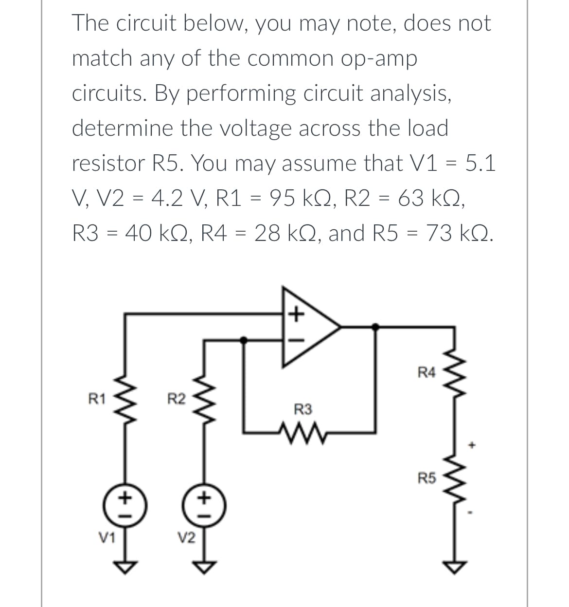
Transcribed Image Text:The circuit below, you may note, does not
match any of the common op-amp
circuits. By performing circuit analysis,
determine the voltage across the load
resistor R5. You may assume that V1 = 5.1
V, V2 = 4.2 V, R1 = 95 kQ, R2 = 63 KQ,
R3 = 40 kQ, R4 = 28 kQ, and R5 = 73 kQ.
R1
V1
R2
V2
+
+
R3
R4
R5
mn m
Expert Solution
This question has been solved!
Explore an expertly crafted, step-by-step solution for a thorough understanding of key concepts.

Step by step
Solved in 3 steps with 2 images

Knowledge Booster


Learn more about
Need a deep-dive on the concept behind this application? Look no further. Learn more about this topic, electrical-engineering and related others by exploring similar questions and additional content below.Recommended textbooks for you
Delmar's Standard Textbook Of Electricity
Electrical Engineering
ISBN:
9781337900348
Author:
Stephen L. Herman
Publisher:
Cengage Learning
Delmar's Standard Textbook Of Electricity
Electrical Engineering
ISBN:
9781337900348
Author:
Stephen L. Herman
Publisher:
Cengage Learning