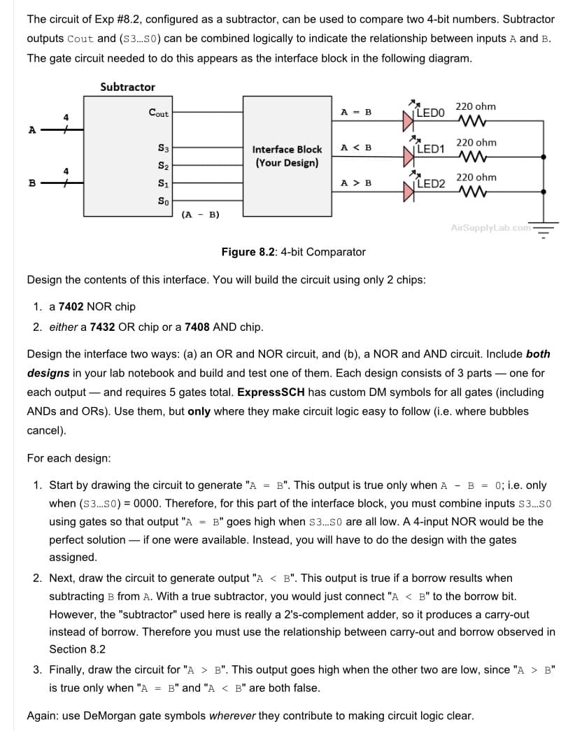
The circuit of Exp #8.2, configured as a subtractor, can be used to compare two 4-bit numbers. Subtractor outputs Cout and (S3.so) can be combined logically to indicate the relationship between inputs A and B. The gate circuit needed to do this appears as the interface block in the following diagram. Subtractor 220 ohm Cout A - B LEDO 4 A S3 A < B LED1 220 ohm Interface Block S2 (Your Design) 220 ohm B S1 A > B LED2 So (A - B) AirSupplyLab.com Figure 8.2


The circuit of Exp #8.2, configured as a subtractor, can be used to compare two 4-bit numbers. Subtractor outputs Cout and (S3.so) can be combined logically to indicate the relationship between inputs A and B. The gate circuit needed to do this appears as the interface block in the following diagram. Subtractor 220 ohm Cout A - B LEDO 4 A S3 A < B LED1 220 ohm Interface Block S2 (Your Design) 220 ohm B S1 A > B LED2 So (A - B) AirSupplyLab.com Figure 8.2: 4-bit Comparator Design the contents of this interface. You will build the circuit using only 2 chips: 1. a 7402 NOR chip 2. either a 7432 OR chip or a 7408 AND chip. Design the interface two ways: (a) an OR and NOR circuit, and (b), a NOR and AND circuit. Include both designs in your lab notebook and build and test one of them. Each design consists of 3 parts – one for each output – and requires 5 gates total. ExpressSCH has custom DM symbols for all gates (including ANDS and ORs). Use them, but only where they make circuit logic easy to follow (i.e. where bubbles cancel). For each design: 1. Start by drawing the circuit to generate "A = B". This output is true only when A - B = 0; i.e. only when (S3.so) = 0000. Therefore, for this part of the interface block, you must combine inputs s3.so using gates so that output "A = B" goes high when s3.so are all low. A 4-input NOR would be the perfect solution – if one were available. Instead, you will have to do the design with the gates assigned. 2. Next, draw the circuit to generate output "A < B". This output is true if a borrow results when subtracting B from A. With a true subtractor, you would just connect "A < B" to the borrow bit. However, the "subtractor" used here is really a 2's-complement adder, so it produces a carry-out instead of borrow. Therefore you must use the relationship between carry-out and borrow observed in Section 8.2 3. Finally, draw the circuit for "A > B". This output goes high when the other two are low, since "A > B" is true only when "A = B" and "A < B" are both false. Again: use DeMorgan gate symbols wherever they contribute to making circuit logic clear.


Trending now
This is a popular solution!

Step by step
Solved in 4 steps with 3 images


