THE CODE HAS TO MULTIPLY 2 NUMBERS TOGETHER. IF YOU DON'T KNOW HOE TO DO THIS PART PLEASE GIVE THE QUESTION TO SOMEONE ELSE. Using C programming language write a program that simulates a variant of the Tiny Harvard Architecture. In this implementation memory (RAM) is split into Instruction Memory (IM) and Data Memory (DM). Your code must implement the basic instruction set architecture (ISA) of the TinyMachine Architecture: 1 -> LOAD 2->ADD 3 ->STORE 4-> SUB 5->IN 6-> OUT 7 -> END 8 -> JMP 9 -> SKIPZ Each piece of the architecture must be accurately represented in your code (Instruction Register, Program Counter, Instruction Memory (IM), MAR1, MDR-1(MAR-1 and MDR-1 are connected to the IM). Data Memory, MAR-2, MDR2 (MAR-2 and MDR-2 are connected to the DM), and Accumulator. Instruction Memory will be represented by an integer array and each instruction will use 2 elements of the array(one for OP and the other one for address) Data Memory will be represented by an integer array and each data value uses an element of the DM array. Your Program Counter will begin pointing to the first instruction of the program (PC-0). For the sake of simplicity Instruction Memory (IM) and Data Memory (DM) may be implemented as separate integer arrays. IM size 250 DM size 10 Hint: All CPU registers and Data Memory (DM) are of type int. Input Specifications Your simulator must run from the command line with a single input file as a parameter to main. This file will contain a sequence of instructions for your simulator to store in "Instruction Memory" and then run via the fetch/execute cycle. In the input file each instruction is represented with two integers: the first one represents the opcode and the second one a memory address or a device number depending on the instruction. YOU MUST MAKE SURE THAT THE PROGRAM BEING RAN MULTIPLIES TWO NUMBERS. YOU CAN USE THE OBJECT FILE BELOW TO HELP WITH THIS. The numbers will not be validated. you can use two integers as inputs 3 and 4. The program must accept the input values in this order input1=0 (to accumulate the result here) input2=1 (top decrement variable that control the loop). input3: first number to be multiplied (for example, 5) input4: second number to be multiplied (for example, 3). Example of reading the object file and printing the Assembly language(this is what should be in the input file): Read Object File 55 67 30 55 67 31 55 67 32 55 67 33 10 22 30 13 41 33 90 812 10 67 70 What the object file above prints: Print it IN 5 OUT 7 STORE 0 IN 5 OUT 7 STORE 1 IN 5 OUT 7 STORE 2 IN 5 OUT 7 STORE 3 LOAD 0 ADD 2 STORE 0 LOAD 3 SUB 1 STORE 3 SKIP 0 JUMP 12 LOAD 0 OUT 7 END Output Specifications The virtual machine(VM) you are implementing should provide output according to the input file. Along with this output your program should provide status messages identifying details on the workings of your simulator. Output text does not have to reflect my example word-for-word, but please provide detail on the program as it runs in a readable format that does not conflict with the actual output of your VM. After each instruction print the current state of the Program Counter, Accumulator, and Data Memory. The INPUT instruction is the only one that should prompt an interaction from the user. Example: Reading Program... Program Loaded. Run. PC 10|A NULL | DM = [0, 0, 0, 0, 0, 0, 0, 0, 0, 0] /* input value */ X PC 12|A=X|DM = [0, 0, 0, 0, 0, 0, 0, 0, 0, 0] /* outputting accumulator to screen */ X PC 14|A=X | DM = [0, 0, 0, 0, 0, 0, 0, 0, 0, 0] /* storing accumulator to memory location 0 */ PC 16|A X | DM = [X, 0, 0, 0, 0, 0, 0, 0, 0, 0] ... etc Program complete. Your program should compile and run from the command line with one input file parameter. For instance, to implement FETCH and instruction LOAD you must implement each step: FETCH MAR1 <-PC PC <- PC+2 MDR1 <- IM [MAR1] // IM stands for Instruction Memory (program memory) IR <-MDR1 Case IR.OP = 1 Load is executed. //LOAD (Execute cycle) MAR2 <-IR.ADDR MDR2 <- DM [MAR2] //DM stands for Data Memory A <-MDR2 Note: you can use MAR or MAR1 for IM and MAR2 for DM. Tiny Machine ISA: FETCH MARI <- PC PC <-PC+2 MDR1 <- IM [MAR] // IM stands for Instruction Memory (program memory) IR <-MDR1 Depending on IR.OP one of the following instructions will be executed: (Execute cycle) LOAD MAR2 <- IR.ADDR MDR2 <-DM[MAR2] A <- MDR2 ADD MAR2 <- IR.ADDR MDR2 <- DM[MAR2] A <-A+MDR2 STORE MAR2 <- IR.ADDR MDR2 <- A DM[MAR2] <- MDR2 SUB MAR2 <-IR.ADDR MDR2 <- DM[MAR2] A <- A - MDR2 IN A <- Input value from keyboard (emit a message to the user: "Input data:”) OUT Screen <-A (emit message to the user: "The result is:" END Run <- 0 // In your program Run must be initialized to 1 to control the instruction cycle. JMP PC <- IR.ADDR SKIP IF (A=0) PC PC + 1|
THE CODE HAS TO MULTIPLY 2 NUMBERS TOGETHER. IF YOU DON'T KNOW HOE TO DO THIS PART PLEASE GIVE THE QUESTION TO SOMEONE ELSE. Using C programming language write a program that simulates a variant of the Tiny Harvard Architecture. In this implementation memory (RAM) is split into Instruction Memory (IM) and Data Memory (DM). Your code must implement the basic instruction set architecture (ISA) of the TinyMachine Architecture: 1 -> LOAD 2->ADD 3 ->STORE 4-> SUB 5->IN 6-> OUT 7 -> END 8 -> JMP 9 -> SKIPZ Each piece of the architecture must be accurately represented in your code (Instruction Register, Program Counter, Instruction Memory (IM), MAR1, MDR-1(MAR-1 and MDR-1 are connected to the IM). Data Memory, MAR-2, MDR2 (MAR-2 and MDR-2 are connected to the DM), and Accumulator. Instruction Memory will be represented by an integer array and each instruction will use 2 elements of the array(one for OP and the other one for address) Data Memory will be represented by an integer array and each data value uses an element of the DM array. Your Program Counter will begin pointing to the first instruction of the program (PC-0). For the sake of simplicity Instruction Memory (IM) and Data Memory (DM) may be implemented as separate integer arrays. IM size 250 DM size 10 Hint: All CPU registers and Data Memory (DM) are of type int. Input Specifications Your simulator must run from the command line with a single input file as a parameter to main. This file will contain a sequence of instructions for your simulator to store in "Instruction Memory" and then run via the fetch/execute cycle. In the input file each instruction is represented with two integers: the first one represents the opcode and the second one a memory address or a device number depending on the instruction. YOU MUST MAKE SURE THAT THE PROGRAM BEING RAN MULTIPLIES TWO NUMBERS. YOU CAN USE THE OBJECT FILE BELOW TO HELP WITH THIS. The numbers will not be validated. you can use two integers as inputs 3 and 4. The program must accept the input values in this order input1=0 (to accumulate the result here) input2=1 (top decrement variable that control the loop). input3: first number to be multiplied (for example, 5) input4: second number to be multiplied (for example, 3). Example of reading the object file and printing the Assembly language(this is what should be in the input file): Read Object File 55 67 30 55 67 31 55 67 32 55 67 33 10 22 30 13 41 33 90 812 10 67 70 What the object file above prints: Print it IN 5 OUT 7 STORE 0 IN 5 OUT 7 STORE 1 IN 5 OUT 7 STORE 2 IN 5 OUT 7 STORE 3 LOAD 0 ADD 2 STORE 0 LOAD 3 SUB 1 STORE 3 SKIP 0 JUMP 12 LOAD 0 OUT 7 END Output Specifications The virtual machine(VM) you are implementing should provide output according to the input file. Along with this output your program should provide status messages identifying details on the workings of your simulator. Output text does not have to reflect my example word-for-word, but please provide detail on the program as it runs in a readable format that does not conflict with the actual output of your VM. After each instruction print the current state of the Program Counter, Accumulator, and Data Memory. The INPUT instruction is the only one that should prompt an interaction from the user. Example: Reading Program... Program Loaded. Run. PC 10|A NULL | DM = [0, 0, 0, 0, 0, 0, 0, 0, 0, 0] /* input value */ X PC 12|A=X|DM = [0, 0, 0, 0, 0, 0, 0, 0, 0, 0] /* outputting accumulator to screen */ X PC 14|A=X | DM = [0, 0, 0, 0, 0, 0, 0, 0, 0, 0] /* storing accumulator to memory location 0 */ PC 16|A X | DM = [X, 0, 0, 0, 0, 0, 0, 0, 0, 0] ... etc Program complete. Your program should compile and run from the command line with one input file parameter. For instance, to implement FETCH and instruction LOAD you must implement each step: FETCH MAR1 <-PC PC <- PC+2 MDR1 <- IM [MAR1] // IM stands for Instruction Memory (program memory) IR <-MDR1 Case IR.OP = 1 Load is executed. //LOAD (Execute cycle) MAR2 <-IR.ADDR MDR2 <- DM [MAR2] //DM stands for Data Memory A <-MDR2 Note: you can use MAR or MAR1 for IM and MAR2 for DM. Tiny Machine ISA: FETCH MARI <- PC PC <-PC+2 MDR1 <- IM [MAR] // IM stands for Instruction Memory (program memory) IR <-MDR1 Depending on IR.OP one of the following instructions will be executed: (Execute cycle) LOAD MAR2 <- IR.ADDR MDR2 <-DM[MAR2] A <- MDR2 ADD MAR2 <- IR.ADDR MDR2 <- DM[MAR2] A <-A+MDR2 STORE MAR2 <- IR.ADDR MDR2 <- A DM[MAR2] <- MDR2 SUB MAR2 <-IR.ADDR MDR2 <- DM[MAR2] A <- A - MDR2 IN A <- Input value from keyboard (emit a message to the user: "Input data:”) OUT Screen <-A (emit message to the user: "The result is:" END Run <- 0 // In your program Run must be initialized to 1 to control the instruction cycle. JMP PC <- IR.ADDR SKIP IF (A=0) PC PC + 1|

Database System Concepts
7th Edition
ISBN:9780078022159
Author:Abraham Silberschatz Professor, Henry F. Korth, S. Sudarshan
Publisher:Abraham Silberschatz Professor, Henry F. Korth, S. Sudarshan
Chapter1: Introduction
Section: Chapter Questions
Problem 1PE

Related questions
Question
IN C ONLY
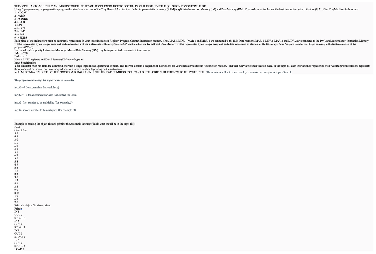
Transcribed Image Text:THE CODE HAS TO MULTIPLY 2 NUMBERS TOGETHER. IF YOU DON'T KNOW HOE TO DO THIS PART PLEASE GIVE THE QUESTION TO SOMEONE ELSE.
Using C programming language write a program that simulates a variant of the Tiny Harvard Architecture. In this implementation memory (RAM) is split into Instruction Memory (IM) and Data Memory (DM). Your code must implement the basic instruction set architecture (ISA) of the TinyMachine Architecture:
1 -> LOAD
2->ADD
3 ->STORE
4-> SUB
5->IN
6-> OUT
7 -> END
8 -> JMP
9 -> SKIPZ
Each piece of the architecture must be accurately represented in your code (Instruction Register, Program Counter, Instruction Memory (IM), MAR1, MDR-1(MAR-1 and MDR-1 are connected to the IM). Data Memory, MAR-2, MDR2 (MAR-2 and MDR-2 are connected to the DM), and Accumulator. Instruction Memory
will be represented by an integer array and each instruction will use 2 elements of the array(one for OP and the other one for address) Data Memory will be represented by an integer array and each data value uses an element of the DM array. Your Program Counter will begin pointing to the first instruction of the
program (PC-0).
For the sake of simplicity Instruction Memory (IM) and Data Memory (DM) may be implemented as separate integer arrays.
IM size 250
DM size 10
Hint: All CPU registers and Data Memory (DM) are of type int.
Input Specifications
Your simulator must run from the command line with a single input file as a parameter to main. This file will contain a sequence of instructions for your simulator to store in "Instruction Memory" and then run via the fetch/execute cycle. In the input file each instruction is represented with two integers: the first one represents
the opcode and the second one a memory address or a device number depending on the instruction.
YOU MUST MAKE SURE THAT THE PROGRAM BEING RAN MULTIPLIES TWO NUMBERS. YOU CAN USE THE OBJECT FILE BELOW TO HELP WITH THIS. The numbers will not be validated. you can use two integers as inputs 3 and 4.
The program must accept the input values in this order
input1=0 (to accumulate the result here)
input2=1 (top decrement variable that control the loop).
input3: first number to be multiplied (for example, 5)
input4: second number to be multiplied (for example, 3).
Example of reading the object file and printing the Assembly language(this is what should be in the input file):
Read
Object File
55
67
30
55
67
31
55
67
32
55
67
33
10
22
30
13
41
33
90
812
10
67
70
What the object file above prints:
Print it
IN 5
OUT 7
STORE 0
IN 5
OUT 7
STORE 1
IN 5
OUT 7
STORE 2
IN 5
OUT 7
STORE 3
LOAD 0
![ADD 2
STORE 0
LOAD 3
SUB 1
STORE 3
SKIP 0
JUMP 12
LOAD 0
OUT 7
END
Output Specifications
The virtual machine(VM) you are implementing should provide output according to the input file. Along with this output your program should provide status messages identifying details on the workings of your simulator. Output text does not have to reflect my example word-for-word, but please provide detail on the program
as it runs in a readable format that does not conflict with the actual output of your VM. After each instruction print the current state of the Program Counter, Accumulator, and Data Memory. The INPUT instruction is the only one that should prompt an interaction from the user.
Example:
Reading Program...
Program Loaded.
Run.
PC 10|A NULL | DM = [0, 0, 0, 0, 0, 0, 0, 0, 0, 0]
/* input value */
X
PC
12|A=X|DM = [0, 0, 0, 0, 0, 0, 0, 0, 0, 0]
/* outputting accumulator to screen */
X
PC
14|A=X | DM = [0, 0, 0, 0, 0, 0, 0, 0, 0, 0]
/* storing accumulator to memory location 0 */
PC 16|A X | DM = [X, 0, 0, 0, 0, 0, 0, 0, 0, 0]
... etc
Program complete.
Your program should compile and run from the command line with one input file parameter.
For instance, to implement FETCH and instruction LOAD you must implement each step:
FETCH
MAR1 <-PC
PC <- PC+2
MDR1 <- IM [MAR1] // IM stands for Instruction Memory (program memory)
IR <-MDR1
Case IR.OP = 1 Load is executed.
//LOAD (Execute cycle)
MAR2 <-IR.ADDR
MDR2 <- DM [MAR2] //DM stands for Data Memory
A <-MDR2
Note: you can use MAR or MAR1 for IM and MAR2 for DM.
Tiny Machine ISA:
FETCH
MARI <- PC
PC <-PC+2
MDR1 <- IM [MAR] // IM stands for Instruction Memory (program memory)
IR <-MDR1
Depending on IR.OP one of the following instructions will be executed:
(Execute cycle)
LOAD
MAR2 <- IR.ADDR
MDR2 <-DM[MAR2]
A <- MDR2
ADD
MAR2 <- IR.ADDR
MDR2 <- DM[MAR2]
A <-A+MDR2
STORE
MAR2 <- IR.ADDR
MDR2 <- A
DM[MAR2] <- MDR2
SUB
MAR2 <-IR.ADDR
MDR2 <- DM[MAR2]
A <- A - MDR2
IN
A <- Input value from keyboard (emit a message to the user: "Input data:”)
OUT
Screen <-A (emit message to the user: "The result is:"
END
Run <- 0 // In your program Run must be initialized to 1 to control the instruction cycle.
JMP
PC <- IR.ADDR
SKIP
IF (A=0) PC PC + 1|](/v2/_next/image?url=https%3A%2F%2Fcontent.bartleby.com%2Fqna-images%2Fquestion%2F44870f31-83c6-452e-ba54-77702704a3ca%2F93e35cde-b46b-4e8d-b416-a989549b5bae%2Frvegf4o_processed.png&w=3840&q=75)
Transcribed Image Text:ADD 2
STORE 0
LOAD 3
SUB 1
STORE 3
SKIP 0
JUMP 12
LOAD 0
OUT 7
END
Output Specifications
The virtual machine(VM) you are implementing should provide output according to the input file. Along with this output your program should provide status messages identifying details on the workings of your simulator. Output text does not have to reflect my example word-for-word, but please provide detail on the program
as it runs in a readable format that does not conflict with the actual output of your VM. After each instruction print the current state of the Program Counter, Accumulator, and Data Memory. The INPUT instruction is the only one that should prompt an interaction from the user.
Example:
Reading Program...
Program Loaded.
Run.
PC 10|A NULL | DM = [0, 0, 0, 0, 0, 0, 0, 0, 0, 0]
/* input value */
X
PC
12|A=X|DM = [0, 0, 0, 0, 0, 0, 0, 0, 0, 0]
/* outputting accumulator to screen */
X
PC
14|A=X | DM = [0, 0, 0, 0, 0, 0, 0, 0, 0, 0]
/* storing accumulator to memory location 0 */
PC 16|A X | DM = [X, 0, 0, 0, 0, 0, 0, 0, 0, 0]
... etc
Program complete.
Your program should compile and run from the command line with one input file parameter.
For instance, to implement FETCH and instruction LOAD you must implement each step:
FETCH
MAR1 <-PC
PC <- PC+2
MDR1 <- IM [MAR1] // IM stands for Instruction Memory (program memory)
IR <-MDR1
Case IR.OP = 1 Load is executed.
//LOAD (Execute cycle)
MAR2 <-IR.ADDR
MDR2 <- DM [MAR2] //DM stands for Data Memory
A <-MDR2
Note: you can use MAR or MAR1 for IM and MAR2 for DM.
Tiny Machine ISA:
FETCH
MARI <- PC
PC <-PC+2
MDR1 <- IM [MAR] // IM stands for Instruction Memory (program memory)
IR <-MDR1
Depending on IR.OP one of the following instructions will be executed:
(Execute cycle)
LOAD
MAR2 <- IR.ADDR
MDR2 <-DM[MAR2]
A <- MDR2
ADD
MAR2 <- IR.ADDR
MDR2 <- DM[MAR2]
A <-A+MDR2
STORE
MAR2 <- IR.ADDR
MDR2 <- A
DM[MAR2] <- MDR2
SUB
MAR2 <-IR.ADDR
MDR2 <- DM[MAR2]
A <- A - MDR2
IN
A <- Input value from keyboard (emit a message to the user: "Input data:”)
OUT
Screen <-A (emit message to the user: "The result is:"
END
Run <- 0 // In your program Run must be initialized to 1 to control the instruction cycle.
JMP
PC <- IR.ADDR
SKIP
IF (A=0) PC PC + 1|
Expert Solution
This question has been solved!
Explore an expertly crafted, step-by-step solution for a thorough understanding of key concepts.

Step by step
Solved in 2 steps

Recommended textbooks for you
Database System Concepts
Computer Science
ISBN:
9780078022159
Author:
Abraham Silberschatz Professor, Henry F. Korth, S. Sudarshan
Publisher:
McGraw-Hill Education

Starting Out with Python (4th Edition)
Computer Science
ISBN:
9780134444321
Author:
Tony Gaddis
Publisher:
PEARSON

Digital Fundamentals (11th Edition)
Computer Science
ISBN:
9780132737968
Author:
Thomas L. Floyd
Publisher:
PEARSON
Database System Concepts
Computer Science
ISBN:
9780078022159
Author:
Abraham Silberschatz Professor, Henry F. Korth, S. Sudarshan
Publisher:
McGraw-Hill Education
Starting Out with Python (4th Edition)
Computer Science
ISBN:
9780134444321
Author:
Tony Gaddis
Publisher:
PEARSON
Digital Fundamentals (11th Edition)
Computer Science
ISBN:
9780132737968
Author:
Thomas L. Floyd
Publisher:
PEARSON

C How to Program (8th Edition)
Computer Science
ISBN:
9780133976892
Author:
Paul J. Deitel, Harvey Deitel
Publisher:
PEARSON

Database Systems: Design, Implementation, & Manag…
Computer Science
ISBN:
9781337627900
Author:
Carlos Coronel, Steven Morris
Publisher:
Cengage Learning

Programmable Logic Controllers
Computer Science
ISBN:
9780073373843
Author:
Frank D. Petruzella
Publisher:
McGraw-Hill Education